


6
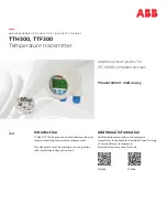
TTH300, TTF300
TEMPERATURE TRANSMITTER | SM/TTX300/SIL-EN REV. E
5
Safety function
The TTH300-*H, and TTF300-*H transmitter are configurable single or dual sensor channel (RTD 2/3/4 wire, TC) digital devices
generating a temperature related analog 4 to 20 mA output signal. The safety function refers strictly to the analog output signal.
The final device assembly consists of the device electronics TTH300-*H, or TTF300-*H, the attached temperature sensor, the housing
with optional connected LCD indicator and the related process connections.
Alarm behavior and alarm current output
When a critical error is detected, an alarm current according NAMUR NE 43 is generated which must be evaluated and processed by
the safety logic solver.
Detected failures by internal diagnostics generates the configured alarm current.
(See Appendix FMEDA Report: Fail detected by internal diagnostics)
There are two selectable modes for the alarm current:
• HIGH ALARM (high alarm, maximum alarm current); this is the factory setting
• LOW ALARM (low alarm, minimum alarm current)
The high alarm current can be configured in a range from 20.0 to 23.6 mA.
The factory setting is 22 mA.
The low alarm current can be configured in a range from 3.5 to 4.0 mA.
The factory setting is 3.6 mA.
In the following cases and by some electrical part failures, an error is forced independently of the configured alarm current to the low
alarm current range:
• Detected runtime errors (e.g., by watchdog)
• Detected memory errors (e.g., non-volatile data, RAM, ROM)
(See Appendix FMEDA Report: Fail low detected by safety logic solver)
Failures in some electrical parts are forcing independently of the configured alarm current the high alarm current range.
(See FMEDA Report: Fail high detected by safety logic solver)
The safety-related system (safety logic solver) must be able to detect both, the high and the low alarm state.
After switching on or restarting the transmitter electronics unit, the minimum alarm time is 10 to 15 seconds.
Overall safety accuracy
The value defined for the overall accuracy of the safety function for this device is ± 2 % of the measuring range.
The basic accuracy depends on the sensor model and is specified in the corresponding data sheets.
Diagnostic test interval
All safety-relevant errors are detected within a diagnostic test interval of 2 minutes.
Type classification
This device is declared as Type B complex element according IEC 61508.
Summary of Contents for TTH300 Series
Page 15: ...TTH300 TTF300 TEMPERATURE TRANSMITTER SM TTX300 SIL EN REV E 15 14Appendix Exida FMEDA Report...
Page 16: ...16 TTH300 TTF300 TEMPERATURE TRANSMITTER SM TTX300 SIL EN REV E 14Appendix Exida FMEDA Report...
Page 17: ...TTH300 TTF300 TEMPERATURE TRANSMITTER SM TTX300 SIL EN REV E 17...
Page 18: ...18 TTH300 TTF300 TEMPERATURE TRANSMITTER SM TTX300 SIL EN REV E 14Appendix Exida FMEDA Report...
Page 19: ...TTH300 TTF300 TEMPERATURE TRANSMITTER SM TTX300 SIL EN REV E 19...
Page 20: ...20 TTH300 TTF300 TEMPERATURE TRANSMITTER SM TTX300 SIL EN REV E 14Appendix Exida FMEDA Report...
Page 21: ...TTH300 TTF300 TEMPERATURE TRANSMITTER SM TTX300 SIL EN REV E 21...
Page 22: ...22 TTH300 TTF300 TEMPERATURE TRANSMITTER SM TTX300 SIL EN REV E 14Appendix Exida FMEDA Report...
Page 23: ...TTH300 TTF300 TEMPERATURE TRANSMITTER SM TTX300 SIL EN REV E 23 Notes...


