


14
TTH200
HEAD-MOUNT TEMPERATURE TRANSMITTER | OI/TTH200-EN REV. B
7
Installation
Installation options
There are three options for installing the transmitter:
• Installation in the cover of the connection head
(without springs)
• Direct installation on the measuring inset (with springs)
• Installation on a top-hat rail
Installation in the cover of the connection head
1
2
3
A10067
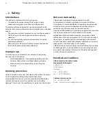
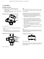
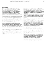
Figure 9: Installation example
1.
Release the screw plug
3
for the cover of the connection
head.
2.
Open the cover
1
.
3.
Secure the transmitter
2
at the proper position on the
cover, using the captive screws found in the transmitter.
Installation on the measuring inset
A10066
1
2
3
4
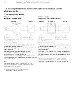
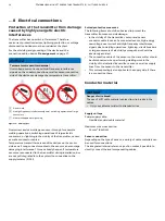
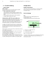
Figure 10: Installation example
Note
Before mounting the transmitter on the measuring inset, remove
the ceramic block on the measuring inset and the captive screws
in the transmitter.
To install the transmitter on the measuring inset, cambered
toothed discs and the corresponding mounting screws are
required; these must be ordered as separate accessories:
Measuring inset installation set (2 fixing screws, 2 springs,
2 toothed discs) order number: 263750
1.
Remove the ceramic block from the measuring inset
3
.
2.
Remove the screws from the transmitter
2
. Remove the
sleeves from the screw holes and then remove the screws.
3.
Insert new fixing screws
1
from above in the fixing holes of
the transmitter.
4.
Place the cambered toothed discs
4
with curve facing
upward on the downward protruding screw thread.
5.
Connect the power supply cable to the transmitter according
to connection diagram.
6.
Place the transmitter in the housing on the measuring inset
and secure it.
Note
The toothed discs between measuring inset and transmitter are
straightened when the screws are tightened. This enables them
to grip the mounting screws.
Installation on the top-hat rail
A10103
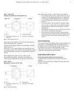
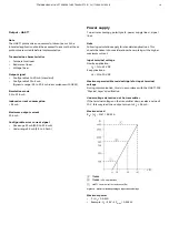
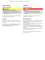
Figure 11: Installation example
When mounted on a top-hat rail, the transmitter can be placed at
a distance from the sensor in a housing that is suitable for the
ambient conditions.


