


Issue 5 - September 2006
Page 14 of 65
The field analogue signal is wired to the Analogue Input Termination Card. Where the safety
integrity levels require that more than one transmitter be used to monitor a safety parameter,
then the additional analogue input signals should be wired to separate Termination Cards where
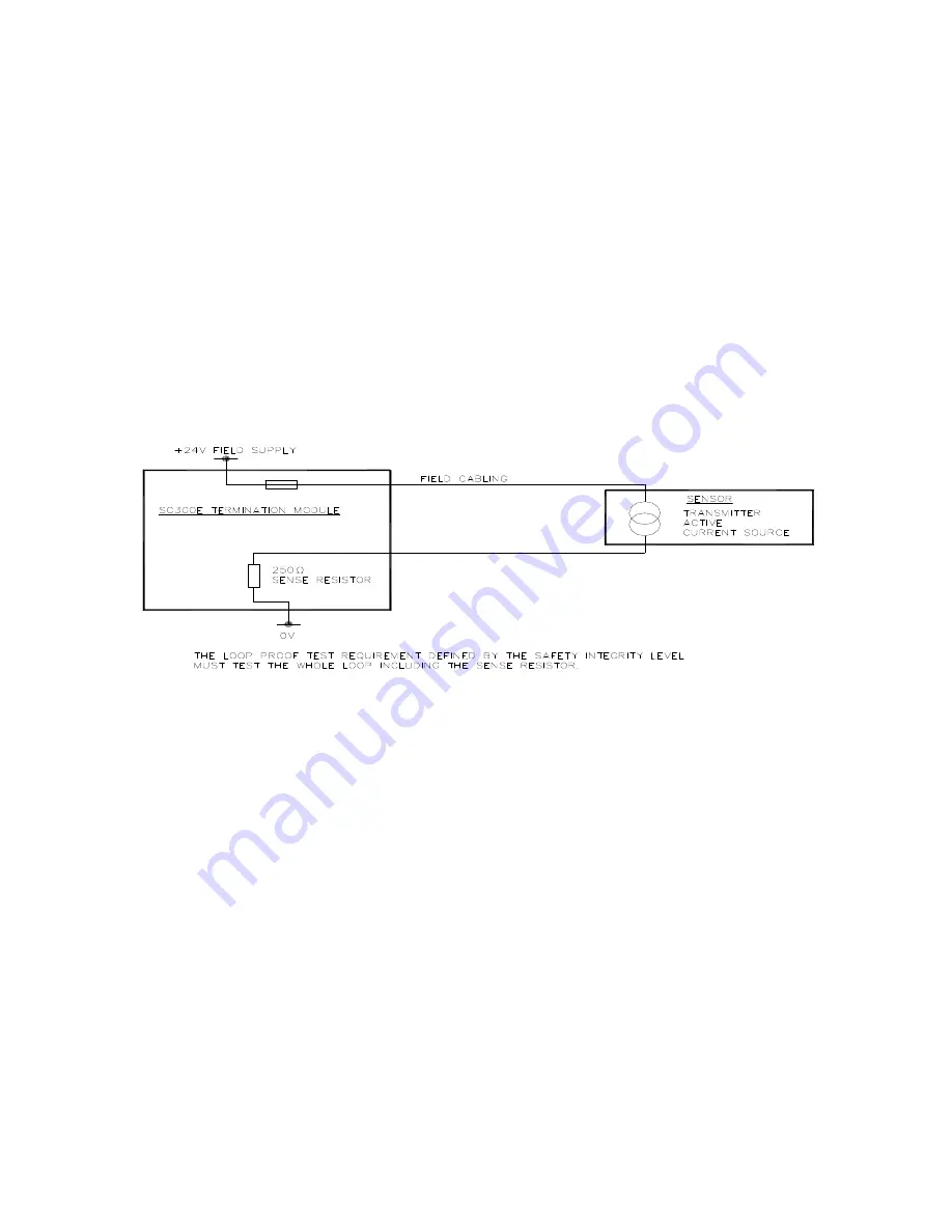
practical. The Simplex circuitry on the termination card must be considered for reliability as part
of the transmitter loop (eg fuses and monitoring resistors where fitted). Refer to Figure 2.
The signal is connected from the termination card to the Triguard SC300E input module via a
standard system cable, which connects to the socket on the appropriate Hot Repair Adapter
Card (THR) or chassis connector.
Through the Hot Repair Adapter Card, where required, and the chassis backplane connector
the input signal is connected to the appropriate configured analogue input module slot position,
where an appropriate Analogue Input Module would be located.
All the chassis slot and, where required, their hot repair partner slots configured for the
Analogue module must also have the coding blocks fitted and configured for this type of module
as specified in the Module and Chassis User Manuals.
Figure 2 Current to Voltage Conversion
Where separate transmitters are used to monitor the same safety parameters to meet increased
integrity levels these should be configured to separate Analogue Input Modules where practical.
Switch inputs with end of line and series line-monitoring resisters fitted may be connected as
analogue inputs. These line-monitored inputs provide increased diagnostic information to the
safety system giving discrete analogue values (step changes) for open circuit, switch open,
switch closed and short circuit conditions.
3.3.1.3 Fail Safe Analogue Processing
For each Analogue Input variable received by the system three values are generated, one from
each channel. Under normal operation (transparent to the application) a mid-value selection
algorithm is used selecting the middle value (assuming all three values are within the health
window) to be passed on to the application. It is this mid-value that the user operates on within
the application, all three processing channels now using this selected mid-value.
When one of the three analogue channel values presented to the processors falls outside of the
health window the processors flag it as bad by converting it to a negative number. If now the
two remaining values diverge by more than the health window these are also flagged as bad by
converting them to negative numbers. The effect is to present to the application a negative
value when 2 or more channels are bad.


