


Description
6
Position Transmitter TGS 40 (RAM)
42/14-50 EN
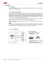
2.4
Connection diagrams
Fig. 2-2 Connection diagram
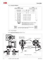
2.5
Dimensional drawings
(dimensions in mm)
2 x Büschelstecker/Brush pin
4 mm (schwarz/black)
Bürklin-Bestellnr./Order No.: 15 F 230
1 x Kupplung/Coupling
∅
∅
4 mm (schwarz/black)
Bürklin-Bestellnr./Order No.: 20 F 100
Kabellänge / cab
le length:
0.5 m
(Bestell-Nr
./Order No
.:
92 F 6751)
Ansicht auf die Lötanschlussenden des Steckereinsatzes
Rear view of connector soldering lugs
HAN 7D
Stecker STH8GS10 / Buchse
Connector STH8GS10 / Socket
HAN 7D
Stecker STH8GP09 / Stifte
Connector STH8GS09 / Pin
nicht belegt / not connected
nicht belegt / not connected
nicht belegt / not connected
nicht belegt / not connected
nicht belegt / not connected
weiß + braun
white + brown
grün / green
gelb / yellow
(0 V)
(24 V DC)
(I
)
mA
1
2
3
4
5
6
7
8
1
2
3
4
5
6
7
8
-U
S
+U
S
+I
A
(- V )
S
(+ V )
S
(+ I )
0
6
5
4
1
7
8
2
3
6
5
4
1
7
8
2
3
ø18
103
149
34
12
69
181
284.5
10
16.5
54
ø34
H8
ø34
H8
ø40
r7
ø40
r7
ø56
r6
ø75
52
4
4
14.5
284
291
Z-17681
EN
Pressure jack
Pressure jack
version SWR
Pressure jack
version HMN and DWR
Flange 1
Flange 2
Direction
of
sight
f
o
r
direction
of
r
atation
Plug connestor HAN 7 D
Harting Co.
Mounting position
Mounting position A
1)
Iron loop
Mounting position B
1)
vertical
1)
Looking towards the flange
Position of the mag-
net and of the
plug with
I
A
= 0 or 4 mA
horizontal
vertical


