ABB SPAM 150 C User Manual And Technical Description Download Page 5

5

U

aux

Auxiliary voltage

A, B, C, D, E, F

Output relays

IRF

Self-supervision

SGB

Switchgroup for the configuration of the blocking or control signal

TRIP

Trip output relay, output 65-66

SIGNAL

Signal on tripping

PRIOR  ALARM

Prewarning for a beginning overload condition

START

Start information from the motor

RESTART ENABLE

Starting of motor inhibited in fault conditions

U1

Motor protection module SPCJ 4D34

U2

Power supply and output relay module SPTU 240 R2 or SPTU 48 R2
with a normally open trip contact, SPTU 240 R3 or SPTU 48 R3 with
a normally closed trip contact

U3

Input  module SPTE 4E3

SPA-ZC—

Bus connection module

SERIAL PORT

Serial communication port

Rx, Tx

Receiver bus terminal (Rx) and the transmitter bus terminal (Tx) of
the bus connection module

STALL

External stall control input

RESTART INHIBIT

External restart inhibit control signal

LATCHING

Latching function of the trip relay

68

69

77

78

80

81

Made in Finland

1

2

3

4

5

6

7

8

9

25

26

27

61

62

63

65

66

74

75

70

71

72

10

11

Serial Port 

SPA 

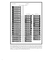
Fig. 3. Rear view of relay SPAM 150 C.

Summary of Contents for SPAM 150 C

Page 1: ...n I s 3I 3 I RS 641 Ser No SPAM 150 C Uaux SPCJ 4D34 REGISTERS OPER IND 0 0 0 0 0 1 2 3 4 5 6 7 8 n L3 n L1 n L2 1 2 3 4 5 6 7 8 o 2 5 9 EXT TRIP 9 t 955D I I I I I I I I I I I 80 265V 18 80V n I I 5A...

Page 2: ...nitoring all three phases the thermal replica is adjustable both for protected objects with or protected objects without hot spots High set overcurrent protection operating in stantaneously or with de...

Page 3: ...ontact functions This contact information is used e g for the blocking of co operating protective re layslocatedupstreams forconnectiontoannun ciator units etc The motor protection relay contains one...

Page 4: ...I START I RESTART INHIBIT RESTART INHIBIT RELAY RESET i a t EXTERNAL TRIP I x t 2 s s 25 26 27 1 2 3 4 5 6 7 8 9 1 A 5 A 1 A 5 A 1 A 5 A 1 A 5 A SERIAL PORT SPA ZC_ Rx Tx 61 62 U aux SGR1 7 SGR1 6 SG...

Page 5: ...and output relay module SPTU 240 R2 or SPTU 48 R2 with a normally open trip contact SPTU 240 R3 or SPTU 48 R3 with a normally closed trip contact U3 Input module SPTE 4E3 SPA ZC Bus connection module...

Page 6: ...odule The communication mode selector switches on the bus connection module are set in position SPA The three phase currents are connected to ter minals 1 2 4 5 and 7 8 when the rated current of the s...

Page 7: ...SGR2 7 SGR1 8 SGR2 3 STALL RESTART INH SGB 3 SGR2 2 1 SG4 3 SG4 2 6x Fig 4 Control signals between the modules of the motor protection relay SPAM 150 C the measuring relay module The functions of thed...

Page 8: ...50Hz 60Hz A The operation indicator TRIP is lit when one of the protection stages operates When the protection stage resets the red indicator remains alight Indication Explanation 1 a The thermal lev...

Page 9: ...x 80 265 V ac dc 18 80 V dc Unstabilized logics voltage Operation amplifier voltage Output relay coil voltage Fig 5 Voltage levels of the power supply module A green LED indicator Uaux on the system f...

Page 10: ...A 1 A 1 A 0 25 A 0 15 A Breaking capacity for ac 5 A 5 A Signalling contacts Terminals 70 71 72 68 69 77 78 80 81 Rated voltage 250 V dc ac Rated current 5 A Make and carry for 0 5 s 10 A Make and ca...

Page 11: ...n unit Setting range for I0 1 0 100 In Operate time t0 0 05 30 s Attenuation of the third harmonic typ 20 dB Phase unbalance unit Basic sensitivity I stabilized to phase current levels below I 10 40 x...

Page 12: ...st IEC 60255 22 2 and IEC 61000 4 2 contact discharge 6 kV air discharge 8 kV Fast transient disturbance test IEC 60255 22 4 and IEC 61000 4 4 power supply 4 kV I O ports 2 kV Mechanical tests tested...

Page 13: ...information about checking overhaul and re calibration of the relay Note Numerical protection relays contain electronic circuitswhichareliabletoseriousdamagedueto electrostatic discharge Before removi...

Page 14: ...over is also IP 54 A terminal strip and two multipole connectors are mounted on the back of the relay case to facilitate all input and output connections To each heavy duty terminal i e the measuring...

Page 15: ...indicator Internal Relay Fault Display 1 3 digits Reset Step push button Programming push button Trip indicator Module type designation Fastening screw Indicators for measured quantities Indicators fo...

Page 16: ...SGB SGR 4 Settings 4 Setting mode 4 Example 1 Setting of relay operation values 7 Example 2 Setting of relay switchgroups 9 Recorded information 11 Trip test function 12 Example 3 Forced activation of...

Page 17: ...ion are accessible in the main menu i e present meas ured values present setting values and recorded parameter values The data to be shown in the main menu are sequentially called up for display by me...

Page 18: ...cation bus 2 By an external control signal BS1 BS2 or RRES BS3 3 Via the push buttons of the relay module see submenu 4 of register A Setting mode Generally when a large number of settings is to be al...

Page 19: ...willshowthreedashes toindicatethenon tripping mode The serial communication is operativeandallmainandsubmenuesareacces sible In the non tripping mode unnecessary trippings are avoided and the settings...

Page 20: ...se L2 Event n 2 value of phase L2 Latest memorized event n value of phase L2 2 1 2 Event n 1 value of phase L3 Event n 2 value of phase L3 Latest memorized event n value of phase L3 3 1 2 Main setting...

Reviews: