


4
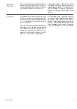
Front paneI
Device symbol
Load current and differential
Self-supervision alarm indicator
current indicators
Display window for set and
measured values
Setting knob and indicator for
the basic setting p
Display step push-button
Setting knob and indicator for
the starting ratio s
Switchgroup for vector group,
Setting knob and indicator for
output relay latching and
the error correction of the
blocking mode selection
transforming ratio of the HV
side current transformers
Switchgroup indicator
Setting knob and indicator for
the error correction of the
Reset push-button
transforming ratio of the LV
side current transformers
Operation indicators
Module type designation
Fig.2. Front panel of the differential relay module SPCD 3C21.
Operation
indicators
issues a control signal to the self-supervision
output relay of the protection unit. Further, in
most fault situations, a fault code showing the
nature of the fault appears on the display of the
module. At a permanent fault, the fault code,
consisting of a red figure one and a green code
number, cannot be erased from the display of
the module by resetting. The self-supervision
alarm is automatically reset when the fault
disappears, but the fault code is maintained on
the display. If the fault has disappeared, the
recorded fault code is reset from the display at
the next pressing of the STEP or the RESET
push-button. When a fault occurs, the fault
code should be written down on a piece of
paper and stated when overhaul is ordered.
The differential relay modules are provided
with a yellow-red operation indicator. When
the differential relay module issues a tripping
signal to the circuit-breaker, the operation
indicator is lit with red light and it remains lit as
long as the tripping signal is reset.
The yellow light of the operation indicator shows
that the CB tripping is blocked by a blocking
function based on the occurrence of the second
harmonic component of the current.
The self-supervision alarm indicator shows
that the self-supervision system has detected
a permanent fault. The indicator is lit with red
light within two minutes after the fault has been
detected. At the same time the relay module
Indicator
Measured data
I
1
The HV side load current I
1
as a multiple of the relay rated current. The
correction setting I
1
/I
n
of the current transformer ratio has been taken
into account in the display.
I
d
The differential current I
d
expressed as a multiple of the relay rated
current.
I
2
The LV side load current I
2
as a multiple of the relay rated current. The
correction setting I
2
/I
n
of the current transformer ratio has been taken
into account in the display.
The measured values are displayed with the
three rightmost digits of the display. The
relevant measured data are indicated by a
LED indicator.
Measured
data
B