Gewährleistung
Das sichere Funktionieren ist dann gewährleistet, wenn die
in dieser Benutzerinstruktion beschriebnen Montagearbei-
ten korrekt ausgeführt worden sind und die Funktionskon-
trolle vor und während dem Betrieb gemäss Beschreibung
in dieser Benutzerinstruktion durchgeführt wird.
Sicherheit
Am Hilfs-/Signalkontakt dürfen keine Reparaturen vorge-
nommen werden.
Entsorgung
Defekte Geräte sind als Sondermüll an entsprechend ein-
gerichteten Sammelstellen zu entsorgen. Nationale oder
regionale Vorschriften über die Entsorgung von Sondermüll
sind zu befolgen.
Funktionsbeschreibung
Hilfskontakte schalten gleichzeitig mit den Kontakten des
Schutzapparates (manuell oder automatisch betätigt).
Signalkontakte schalten bei elektrischer Auslösung des
Schutzapparates infolge Kurzschluss oder Fehlerstrom.
Pro Schutzapparat sind montierbar:
1 Hilfskontaktblock
oder
1 Signalkontaktblock
oder
2 Hilfskontaktblöcke
oder
1 Hilfs- und 1 Signalkontaktblock.
Funktionsprüfung
Nach der Montage muss das richtige Funktionieren der
Hilfs- und Signal kontakt blöcke überprüft werden.
Prüfen Sie zusätzlich mit einem geeigneten Prüfgerät, ob
die Hilfs- und Signal kontakte richtig geschaltet haben. Bei
den Signalkontaktblöcken muss das orange Knöpfchen
deutlich herausragen.
Durch Drücken des weissen Test-Knopfs muss der Kontakt
schalten. Nach jeder Auslösung ist der Kontakt mit Hilfe
des orangefarbenen Reset-Knopfs wieder in die Ausgangs-
lage zu bringen.
Hilfs- und Signalkontaktblock
Bloc de contact auxiliaire et de signalisation
Auxiliary and signal contact blocks
Contatto ausiliario e di segnalazione
2CCC404012M0104 (20V3500.d)
Par la pression du bouton-test gris, le contact de signalisation
doit s’enclencher. Après chaque déclenchement, il faut
ramener le contact de signalisation en position initiale à
l’aide du bouton Reset de couleur orange.
Mise en place des contacts auxiliares et de
signalisation sur l'appareil:
Disjoncteur de ligne au choix à gauche ou à droite
Interrupteur différentiel 4 pôles à droite
Interrupteur différentiel 2 pôles à droite
Interrupteur différentiel/disjoncteur de ligne à droite
Les contacts auxiliaires et de signalisation pour
profilé support SMISSLINE CLASSIC ne peuvent être
montés sur des systèmes enfichables SMISSLINE.
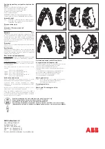
Montage à droit
Fig. 1 Mettre en place la tige de liaison conformément
à l'établissement du contact de l'interrupteur
différentiel ou du disjoncteur de ligne.
Démontage à droit
Fig. 2
Montage / Démontage à gauche
Fig. 3 / Fig. 4
Guarantee
The safe operation is assured if the assembly work has
been carried out according to these user instructions.
Safety
Repairs may not be carried out to auxiliary/signal contacts.
Disposal
Faulty products should be treated as hazardous waste and
disposed of in an appropriate manner. National or regional
regulations regarding the disposal of hazardous waste
should be adhered to.
Function description
Auxiliary contacts switch simultaneously with the contacts of
the protective device (actuated manually or automatically)
Signal contacts operate only when the protective device
has electrically tripped due to short circuit or
residual
current.
The following can be installed per protective device:
1 auxiliary contact block
or
1 signal contact block
or
2 auxiliary contact blocks
or
1 auxiliary and 1 signal contact block.
Function test
After assembly, the correct functioning of the auxiliary and
signal contact blocks must be checked. Check also, by
means of suitable testing equipment, whether the auxiliary
and signal contacts have switched correctly. For the signal
contact blocks, the orange button must clearly protrude.
When the grey test button is pressed, the signal contact
must operate. After each operation, the signal contact must
be reset, by means of the orange-coloured reset button.
Plazieren von Hilfs- oder Signal kontakte
am Gerät:
Leitungsschutzschalter wahlweise links oder rechts
4poliger Fehlerstromschutzschalter rechts
2poliger Fehlerstromschutzschalter links
Fehlerstrom-Leitungsschutzschalter links
Hilfs- und Signalkontakte SMISSLINE CLASSIC Trag-
schienen-Geräte sind nicht an SMISSLINE Geräte Steck-
systeme anbaubar.
Montage rechts
Fig. 1 Verbindungsstift bei Version Rechts, für Anbau
LS oder FI4, entsprechend entfernen.
Demontage rechts
Fig. 2
Montage / Demontage links
Fig. 3 / Fig. 4
Garantie
Le bon fonctionnement est garanti lorsque les opérations de
montage décrites dans ces instructions ont été effectuées
correctement et que les contrôles de bon fonctionnement
ont été faits avant et pendant
l'exploitation selon la
description donnée dans les présentes instructions.
Sécurité
Ne procéder à aucune sorte de réparation sur les contacts
auxiliaire/signalisation.
Elimination
Les appareils défectueux sont à éliminer en tant que
déchets spéciaux sur les lieux de collecte prévus à cet effet.
Respecter les prescriptions nationales ou régionales.
Description de fonctionnement
Les contacts auxiliaires commutent simultanément
avec les contacts de l'appareil de protection (actionnés
manuellement ou automatiquement).
Les contacts de signalisation commutent en cas de
déclenchement de l'appareil de protection à la suite de
court- circuit ou de courant de défaut.
Par appareil de protection, on peut monter:
1 bloc de contact auxiliaire
ou
1 bloc de contact de signalisation
ou
2 blocs de contact auxiliaires
ou
1 bloc de contact auxiliaire et
1 bloc de contact de signalisation.
Test de fonctionnement
Après le montage, le bon fonctionnement du bloc de
contact auxiliaire et de signali sation doit être testé. Vérifiez
aussi avec un appareil approprié si les contacts auxiliaires
et de signalisation ont commuté. Sur les blocs de contact
de signalisation, le petit bouton orange doit faire clairement
saillie.
Jan. 2016


