


Mounting and installation
42/14-36 EN
Thermal Mass Flowmeter FMT400-VTS, FMT400-VTCS (Sensyflow VT-S/VT-CS)
21
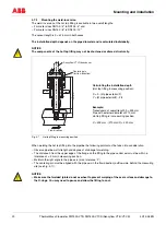
4.7.4
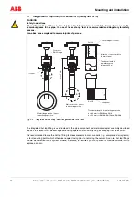
Mounting the transducer with system in operation
– The hot tap fitting must be in disassembly position (Fig. 4-6), i.e., Sensyflow opening is sealed.
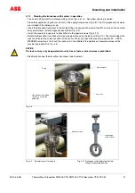
– Place the supplied O-ring (55 mm x 3 mm) in the appropriate groove (Fig. 4-8). The O-ring gasket and screws
are included in the delivery scope.
– Insert the Sensyflow transducer in the hot tap fitting and secure with screws (two M12 screws and two extend-
ed special screws, installed opposite each other (Fig. 4-9).
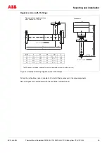
– Install the covers and use nuts to attach them to the special screws (Fig. 4-10).
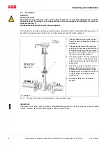
– Rotate the Sensyflow transducer into measuring position using the lock nut (Fig. 4-10). The lower edge of the
lock nut indicates the current position of the sensor. When you reach the measuring position 50 - OPEN -
MESSEN (lower stop of lock nut), the sensor is in the middle of the pipeline and accurate values will be
provided (see detail A in Fig. 4-4).
NOTICE
The lock nut may only be operated manually. Use of tools or other devices is prohibited.
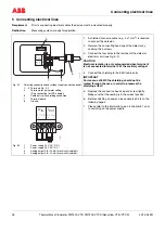
– Electrically connect the Sensyflow transducer (see chapter 5)
Fig. 4-8
Fig. 4-9
Special screws for covers
Fig. 4-10 Transducer with integrated hot top-
fitting in measuring position
!
Centering pin
Lock nut
O ring
Hex-head socket screws
(4 units) to secure the
guide tube
Special screws
Lower edge
of the lock nut