


Connecting electrical lines
26
Thermal Mass Flowmeter FMT400-VTS, FMT400-VTCS (Sensyflow VT-S/VT-CS)
42/14-36 EN
5 Connecting electrical lines
Requirement
Prior to connecting electrical cables the device must be mounted properly.
Destination
Measuring system is ready for operation.
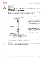
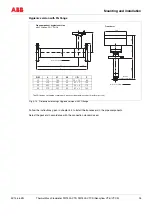
Fig. 5-1
Detecting connection head (without cap of connection head)
1 ... 4 Terminals Fig. 5-2
5
Terminals for parameter setting
(Plug connection for LKS adapter)
6
Cable entry with shielding connected
7
Terminal board
8
Ground
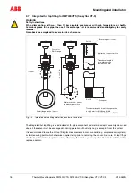
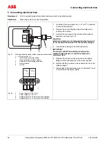
Fig. 5-2
1
Power supply 24 V AC / DC +
2
Power supply 24 V AC / DC -
3
Analog output 0/4...20 mA (electrically isolated) +
4
Analog output 0/4...20 mA (electrically isolated) -
1.
A shielded, four-wire cable (e. g. 4 x 1 mm
2
) is required
to connect the detector.
2.
Remove the connecting head cap of the detector by
undoing the 4 screws.
3.
Connect the four wires to the terminal of the detector
electronic unit (see Fig. 5-2).
CAUTION
Electrical isolation is only safeguarded when terminal 4
is not connected to terminal 2 of the auxiliary voltage!
4.
Connect the shielding to the EMC cable entry.
IMPORTANT
For reasons of EMC the shielding should not be
routed through the case, in order to preserve the
shielding effect!
5.
Replace the connection head cap and screw tightly.
Make sure that the sealing is in the correct position.
6.
Before switching on power, please observe hints on the
following pages.
7.
Please refer to the information given in chapter 5.1 prior
to switching on the power supply.
12
3
4
U
IN
I
OUT
24
V
AC/DC
0/4...
20
mA
+
+
-
-
5
6
7
8
Z-18986
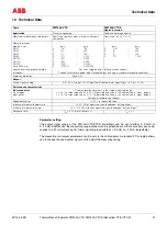
1
2
3
4
U
IN
I
OUT
24 V AC/DC 0/4...20 mA
+
+
-
-
Z-18987