42/23-51 EN Rev. 3
SCC-F Sample gas feed unit Operator’s manual
15
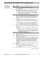
Connecting the electrical leads: SCC-F without I/O card
Connecting the
electrical leads
(see Figures 3, 4 and 5)
Step Action
Connect signal and control leads to the sample gas feed unit:
1
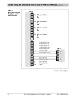
Connect the status signal leads of the condensate and flow monitoring
to terminal strip
X3
.
2
If necessary connect the external control leads (230 VAC, max. 1 A) of
the diaphragm pumps and the dosing pump to terminal strip
X4
.
Before connecting the leads remove the factory-installed wire
jumpers from the respective terminals. Do not remove the wire
jumpers from the unused terminals.
If necessary connect the sample gas cooler to the sample gas feed unit:
3
Side-by-side installation: Pull the connection cables for temperature
alarm and power supply of the sample gas cooler (delivered with the
unit, see section “Scope of delivery”, page 8) through the rubber
bushing.
4
Connect the 2-wire connection cable for the temperature alarm
to terminals 4 and 8 on terminal strip
X4
in the sample gas feed unit
and
to terminals 2 and 3 on terminal strip
X3
in the sample gas cooler.
If the sample gas cooler is provided with a signal cable wires
2 (C) and 3 (NO) of this cable can be used for this purpose.
5
Connect the 3-wire connection cable for the sample gas cooler’s power
supply
to terminals 1, 2 and 3 on terminal strip
X1
in the sample gas feed
unit and
to terminals 2, 3 and 4 on terminal strip
X1
in the sample gas cooler.
If the sample gas cooler is provided with a power supply cable
this cable can be used to connect the sample gas feed unit to
the power supply (see step 9).
Connect the power supply to the sample gas feed unit::
6
Make sure the voltage setting shown on the rating plate matches
the line voltage.
7
Make sure the power supply leads have an adequately dimensioned
protective device (breaker).
8
Install a switched outlet or a breaker in the power supply wiring near
the sample gas feed unit. This should allow the sample gas feed unit to
be completely disconnected from the power supply if necessary. The
disconnection device should be identified in such a way that its
relationship to the equipment that it is designed to disconnect can be
clearly seen.
9
Connect the power supply leads to terminals 4, 5 and 6 on terminal
strip
X1
.
10
Connect the power supply leads to the power supply.
The sample gas feed unit may start when the power supply is
connected.
Continued on next page


