


42/23-55 EN Rev. 1
SCC-C Sample Gas Cooler Operator’s Manual
15
Removing and Installing Heat Exchangers,
continued
Step Action
Install the heat exchanger:
7
Insert the heat exchanger in the opening in the cooling block
3
and,
turning it slightly, push it downwards right to the limit stop.
8
Remove the adhesive tape from the condensate outlet on the heat
exchanger and remove any thermal conductive paste that has been
squeezed out.
Connect the sample gas and condensate pipes to connections
1
and
2
respectively of the heat exchanger.
9
Note the following points when installing a glass heat exchanger:
Before fitting the GL coupling nuts you should check that the
PTFE / silicone compression fittings are not damaged. The com-
pression fittings should be fitted with their PTFE surface facing
the glass. The GL coupling nuts should be hand-tightened.
10
Ensure that the temperature sensor
4
is inserted in the cooling block
all the way to the limit stop.
Start the sample gas cooler again:
11
Verify the integrity of the open gas path.
12
Switch power supply to sample gas cooler back on.
13
The sample gas flow should only be restarted after the lead time
period.
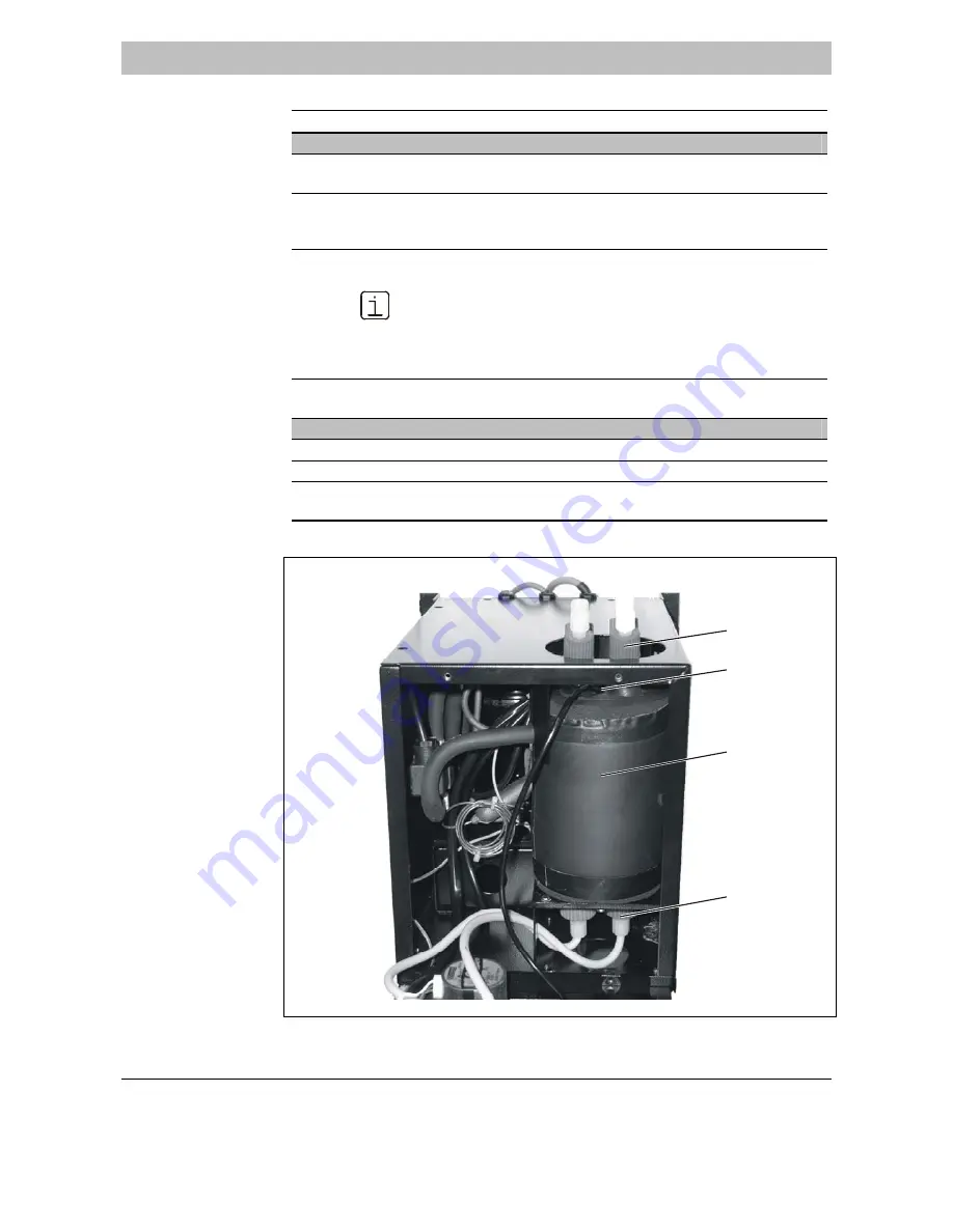
Fig. 4
Sample Gas Cooler,
Front View, with
Front Cover Open
1
4
3
2
1
Heat Exchanger Sample Gas Connections
2
Condensate Connections of the Heat Exchangers
3
Cooling
Block
4
Temperature
Sensor