background image

37

I N S TA L L AT I O N  A N D  O P ER AT I N G  I N S T R U C T I O N S

14.3  Putting into service 

Preparatory work 

Before connection to the medium voltage network the  
following work must be carried out in preparation for  putting 
into service: 
•   Check the general condition of the switchgear for any   

damage or defects. 

•   Visually inspect the switching devices, cable bushings,     

insulating parts, etc. 

•   Check the paintwork for any damage and, where neces- 

sary paint over scratches to avoid corrosion 

•   Remove all residues of materials, foreign objects and  

tools from the switchgear. 

 •   If necessary, clean the switchgear and remove any  traces 

of greasy or sticky dirt. 

•   Correctly remount all covers etc. removed during   

assembly and testing procedures. 

•   Switch the auxiliary and control voltage on. 
•   Carry out testing operations on switching devices either 

manually or using electrical control, simultaneously  
observing the relative position indicators. 

•   Check the mechanical and electrical interlocks for               

effectiveness, without using force. 

•   Check the SF

6

 gas pressure of the tank. It needs to be at  

green level before operating the switchgear. 

•   Instruct local operators regarding the basic features for  

correct use of the switchgear. 

Other checkpoints 

•   Depending on the allocation of responsibilities, it may 

also be necessary to check the following equipment in  the 
vicinity of the switchgear: 

•   Power cables 
•   Auxiliary cables 
•   Auxiliary power source 
•   Remote control system 
•   Complete earthing system 
•   Switchgear installation room equipment 
•   Switchgear installation room characteristics: 

-  Pressure resistance in the case of an arc fault 
-   Ventilation 
-   Temperature 
 -   Humidity 

14.4  Start-up 

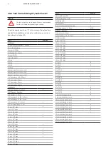
Instructions 

Comply with all relevant safety regulations. 
Ensure that the Load break switches, switch-disconnectors, 
circuit-breakers in the configuration are in the OPEN position. 
Energize the power supply feeders. Connect the switchgear  
step by step, observing the signals and indicators. 
Where necessary, check that the conductors are in phase  
when there are several incoming feeder cables and  
switchgear sections. Carry out all measurements and check  
that all functions that depend on the medium voltage power  
supply are connected. Check there are no irregularities of  
any kind. 

Summary of Contents for SafeRing XT

Page 1: ...SafeRing XT SafePlus XT Installation and operating instructions Compact and Smarter No live parts exposed High reliability and safety Safe and easy for operators in both maintenance and operating con...

Page 2: ...g XT SafePlus XT can be supplied in a number of different configurations suitable for most switching applications in 12kV distribution networks Digital solutions like smart automation control and moni...

Page 3: ...ansport and handling 12 13 3 1 Packing 3 1 2 Transport 3 1 3 By receiving inspection 3 2 Storage 3 2 1 Intent 3 2 2 Codes and standards 3 2 3 Storage condition 4 Technical data 14 4 1 Electrical data...

Page 4: ...9 1 External busbar 10 Current and voltage transformers 30 31 11 Motor operation 32 12 Protection 33 13 Pressure indicator 34 35 13 1 Gas pressure 13 2 Altitude 13 2 1 Adjustment of gas pressure in hi...

Page 5: ...19 1 Procedure for switchgear with test points 19 2 Procedure for testing directly on the cable connector with the cable connected to the switchgear 20 Service and maintenance 46 49 20 1 General warn...

Page 6: ...r s personnel are responsible for all matters regarding safety in the workplace and correct use of the switchgear 1 3 Crucial information Pay special attention to the information shown in the manual b...

Page 7: ...ds and Initiate the Permit To Work PTW process STEP 2 Clearly identify the work location and equipment Use your senses to identify problem areas Define the work area via barriers and barricading and l...

Page 8: ...nicians engineers and approved channel partners Certification to perform installation and commissioning maintenance and repairs extension upgrade and retrofit end of life services and replacements at...

Page 9: ...y due to its extendibility and the possible combination of fully modular and semi modular configurations with a maximum of 5 modules in one SF6 tank The units are delivered from the factory ready for...

Page 10: ...nnector Operation handle access 10 Switch Disconnector Operation selector knob 11 Fault passage indicator 12 VCB Push button Open Close 13 Spring Charging Indicator 14 VCB Open Close Indicator 15 Volt...

Page 11: ...g Module 1 Lightning arrester jumpers 2 Lightening arrester 3 Insulating boots 4 R Y B jumpers assembly 5 Extension bushing assembly 6 Lifting angle lugs 7 Auxiliary PT 8 12 kV PT 9 Low voltage and ba...

Page 12: ...y such damage has occurred a claim must be submitted to the carrier immediately After unpacking the following must be checked 1 Operating handle A one piece is included normally fixed on inside of mai...

Page 13: ...store the unit under covered area in a dry and well ventilated area until it is installed and put into operation Although product is outdoor it is recommended to avoid storage of the packed unit unde...

Page 14: ...sconnector kVp 110 110 110 Rated normal current A 630 630 Rated frequency Hz 50 50 50 50 Breaking capacities Active load breaking current A 630 Closed loop breaking current A 630 Cable charging breaki...

Page 15: ...NOTE The tools required for installation and maintenance of the switchgear are specified in the tool list in chapter 20 6 Unit A B C D E 1 way 340 190 290 170 85 2 way 665 515 615 325 170 3 way 990 84...

Page 16: ...3 Way Ring Main Unit Metering Module Ring Main Unit 1 Refer Chapter 5 1 NOTE The unit must be fixed using the bolts shown in the position in red Use M10 or M12 screws NOTE The tools required for insta...

Page 17: ...Hex Nut Foundation Bracket of RMU M10 Hot Dip Galvanized Cup Washer Hot Dip Galvanized M10x100 Anchor Bolt Maximum limit is 60mm 40mm Hot Dip Galvanized M10x100 Anchor Bolt Foundation Bracket of RMU 4...

Page 18: ...re preliminary and may change after final design preparation based on final scope of supply and installation details of the switchgear As a consequence provided values of dimensions and weights are NO...

Page 19: ...e Melting decomposing and evaporation of materials Tested according to IEC standard 62271 200 The capability of SafeRing XT SafePlus XT switchgear to withstand internal arc is proven by type tests per...

Page 20: ...the basic parameters below Basic parameters of set up IAC AFLR up to 10 kA 0 1s 21kA 1s Minimum height of ceiling 3000 mm Recommended distance to Rear Lateral wall 800 mm with accessible Rear Lateral...

Page 21: ...be open when Disconnector or Switch disconnector is in Off or On condition 2 Cable door Can be opened only when particular module earth switch is in On position 3 Once the door is open Disconnector or...

Page 22: ...then Push inside 3 Slide down 10 12mm the door completely till it locks and engage properly with cable compartment slots 4 Cable door can t be refix when Disconnector or Switch disconnector is in Off...

Page 23: ...ector operation selector knob 3 Defeat Interlock Plate 4 Handle for defeat Interlock 5 Clockwise rotation blocking pin for V module selector knob Blocks the clockwise rotation for V module selector kn...

Page 24: ...in reverse direction Ensure the Switch Disconnector Disconnector of respective module is in Earth position iii Dis engage the defeat interlock from flange C ii Lift the Defeat interlock 10 12mm i Pul...

Page 25: ...phase positions sequence 3 Cables correctly clamped and gland area sealed properly to avoid dust verm entry All 3 cables in 3 core terminations cut and adjusted properly so that cable lug hole and M16...

Page 26: ...n integrated earthing wire Delivered in 3 phase kits complete with cable lugs bolt connection and stress grading adapter designed to ensure a reliable installation Screened touchproof separable connec...

Page 27: ...following manufacturers of cable terminations are recommended SafeRing XT screened termination kit suitability Single Cable Double cable 1 Cable Surge arrester Sr No Make Company Model Model Model 1...

Page 28: ...termination remove the bottom cover of the RMU for easy routing pulling of cables Ensure once termination is completed bottom cover is refixed with proper hardware as per table WASH N_ISO7089_8x16x1 6...

Page 29: ...OPER ATING INSTRUCTIONS 9 Extension of switchgear Figure 9 1 Coupled SafePlus XT 3 way unit CCV CCV 9 1 External busbar SafePlus XT can be equipped with a side extension See separate document 2REA063...

Page 30: ...he easy termination of cables adjustable arrangements are given for current transformers A Up Down Front Rear adjustments are possible NOTE Make and size of the CT s shown for representative purpose o...

Page 31: ...the hardware 6 Then fix the upper CT Engage the teeth of the CT plate with the slot and then tightened the hardware Figure 10 5 CT Fixing Step 04 Figure 10 6 CT Fixing Step 05 Each current transformer...

Page 32: ...ed behind the front mimic The mechanisms for all the switches and breakers are operated manually with the operating lever standard or are fitted with motor operation additional equipment For upgradati...

Page 33: ...ave been delivered and that they are all of the same type Check that the current transformers are of the correct type with the correctly rated transformer ratio for the distribution transformer s rate...

Page 34: ...with a nominal pressure of 1 3 bar absolute at 20o C SafeRing XT SafePlus XT are sealed for life and fitted with a temperature compensated pressure indicator WARNING Operation when pressure is too lo...

Page 35: ...e sealing between the pressure indicator and the valve is smooth and clean and screw the pressure indicator to the RMU switchgear with tightening torque max 45 Nm as shown below Figure 13 4 Unscrewing...

Page 36: ...follows Testing of the switching device or the vacuum interupter to VDE 0671 part 100 or IEC 62271 100 at the relevant rated power frequency withstand voltage may only be performed by trained personn...

Page 37: ...SF6 gas pressure of the tank It needs to be at green level before operating the switchgear Instruct local operators regarding the basic features for correct use of the switchgear Other checkpoints De...

Page 38: ...r OFF ON Earth Figure 15 1 ON OFF EARTH indications Figure 15 2 C Module switch disconnector in OFF position Figure 15 3 C Module selector knob Figure 15 4 Operation of C Module switch disconnector Fi...

Page 39: ...ystem The Switch disconnector is only switched after pressing these buttons Red A push button for switch Off the Switch disconnector Green B push button to switch On the Switch disconnector A Green pu...

Page 40: ...ndicator will indicate discharged 6 If the vacuum circuit breaker is equipped with motor operation optional it is not necessary to charge the spring by hand The motor starts charging the spring automa...

Page 41: ...handle To Close Turn the operating handle clockwise To Open Turn the operating handle anti clockwise Earthing switch Operation Selector Knob Rotate clockwise then insert operating handle To Close Tur...

Page 42: ...remove the front mesh C DANGER Make sure there is no voltage in the busbars and cable terminals and that the risk of reconnection is eliminated in all units Any remote control must also be prevented D...

Page 43: ...ecessary to improve visibility by additional means Operating temperature The VPIS will operate reliably over a temperature range of 25 C to 50 C Phase comparison and testing of VPIS Each phase of the...

Page 44: ...is obtained by opening the top front LV door panel A A shunt trip coil and Close coil AC or DC can be fitted on V Module Circuit breaker 18 2 Remote control and monitoring unit SafeRing XT SafePlus XT...

Page 45: ...for testing directly on the cable connector with the cable connected to the switchgear 1 Open switch disconnector disconnector 2 Check voltage status 3 If voltage is not present close the earthing sw...

Page 46: ...out always depend on the operating conditions of the switchgear and above all on the mode of operation the number of rated and short circuit current switching operations ambient temperature pollution...

Page 47: ...charges occur as a result of condensation application of a thin silicone film over the surface concerned is often effective as a temporary remedy It is advisable to ask the ABB after sales service dep...

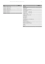
Page 48: ...plier ergo X Strippling plier X Universal plier Bits set with screwdriver handle X 3 8 Long ratchet L 50 cm X 3 8 Pipe set Content 3 8 ratchet L 24 cm 3 8 extender L 3 7 5 cm 3 8 Bits holder 8 mm 3 8...

Page 49: ...key set 1 5 10 mm Tools Required Extra tools Head lamp LED Flashlight LED Multi purpose service spray 5 56 Permanent Marker Small cable ties L 203 x 2 5mm Large cable ties L 375 x 7 6mm Multimeter UT5...

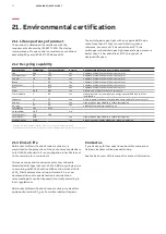
Page 50: ...n quartz 15 3 6 Yes Grind to powder and use as high grade energy additive in cement mill Rubber 2 2 2 Yes High grade energy additive in refuse incineration SF6 gas 2 7 0 6 Yes ABB India Ltd reclaims u...

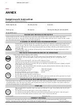
Page 51: ...discharge SF6 into the atmosphere Use an SF6 servicing unit with filler system Check the connections for gas tightness Work which generates strong heat e g welding is prohibited Do not smoke eat drin...

Page 52: ...ystem room Opening of and working on or in opened SF6 gas compartments additional measures please complete and delete where not applicable Only open SF6 gas compartments after complete empyting and eq...

Page 53: ...abb com...

Page 54: ...abb com...

Page 55: ......

Page 56: ...be pleased to help ABB India Ltd ELDS Plot No 79 Street No 17 MIDC Satpur Nashik 422 007 Maharastra India www abb com medium voltage switchgear Copyright 2022 ABB All rights reserved Specifications su...

Reviews: