abb
SafeLink
SF
6
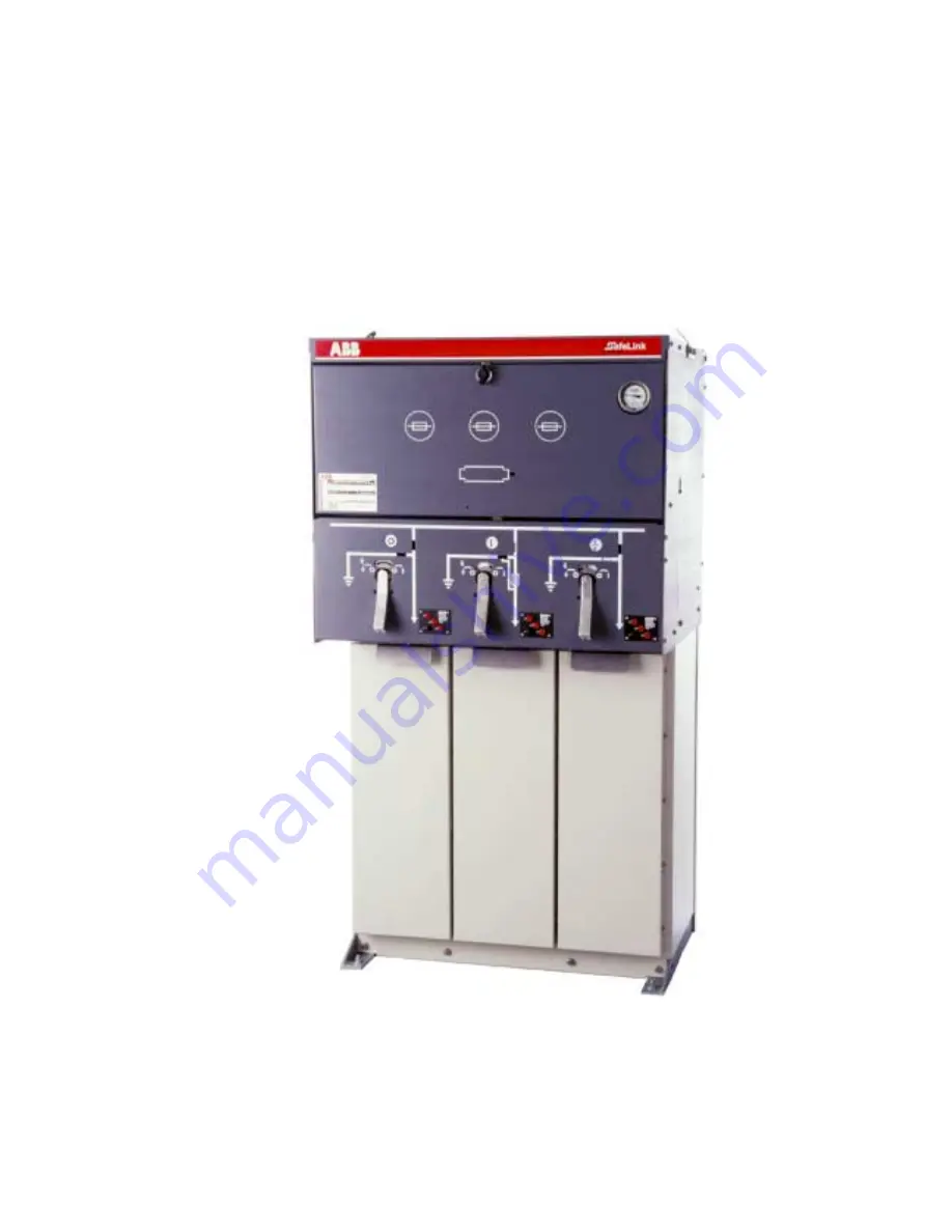
Insulated Ring Main Unit
Installation and Operating
Instructions
Switchgear DivisionAuckland, New ZealandSLMIO ver 2.12
Page 1: ...abb SafeLink SF6 Insulated Ring Main Unit Installation and Operating Instructions Switchgear Division Auckland New Zealand SLMIO ver 2 12 ...
Page 2: ... ISO9001 Quality and ISO14001 Environmental SafeLink equipment conforms to all applicable IEC standards This manual provides detailed information on the handling installation commissioning and operation of SafeLink The range of SafeLink products and the specifications of the equipment are subject to change without notice as product features and benefits are added For more information or to discuss...
Page 3: ..._______ 8 2 3 1 Steps for Fuse Replacement ____________________________________ 8 2 4 Fuse Link Selection _____________________________________ 10 2 5 Cable Box _____________________________________________ 11 2 6 Cable Testing __________________________________________ 11 3 Maintenance__________________________________________ 12 3 1 Environmental _________________________________________ 12 3 2 ...
Page 4: ...______________________ 7 Figure 7 Front of SafeLink unit showing the mimic diagram for the switch fuse following a fuse blow event Note the word RESET and the red fuse blown indicator are displayed _________________________________________________________ 8 Figure 8 Fuse door open and fuse canisters available _________________________ 8 Figure 9 Central fuse assembly and fuse being withdrawn _____...
Page 5: ...ble in the round hole towards the top of the mimic panel and confirmed by the mimic diagram Active flags in the diagram match the circuit condition with black confirming open switches and white indicating switches that are closed Access to the cable box and fuse compartment is interlocked with the switch status The operating handle is designed to give a delay between switching operations Insertion...
Page 6: ... Current 400A or 630A Withstand Current 16kA rms or 20kA rms Withstand Current Duration 3sec Recommended Maximum Cable Size 300mm 3 core cable 500mm single core cable Load Break Switch E3 M2 rating to IEC 60265 1 1998 Rated Current 400A or 630A Short Circuit Making Current 40kA peak or 50kA peak Switch Fuse Rated Current 200A Prospective Fault Withstand 20kA rms Max Transformer size 1000kVA Bushin...
Page 7: ...1 4 Standard Compliance SafeLink has been tested to and passed the following standard tests in an ASTA accredited laboratory IEC 60298 1990 12 A C metal enclosed switchgear and controlgear for rated voltages above 1kV and up to and including 52kV IEC 60265 1 1998 01 High voltage switches Part 1 Switches for rated voltages above 1kV and less than 52kV IEC 60420 1990 10 High voltage alternating curr...
Page 8: ...Operating Instructions SLMIO ver 2 12 ABB Ltd Switchgear Division Auckland New Zealand 4 1 2 Arrangement Drawings 1 2 1 General Arrangement Figure 2 SafeLink general arrangement 1 2 2 Foundation Plan 13 diameter mounting holes Figure 3 SafeLink foundation plan ...
Page 9: ...ons SLMIO ver 2 12 ABB Ltd Switchgear Division Auckland New Zealand 5 1 2 3 Schematic Figure 4 SafeLink schematic diagram CFC configuration Note that the switch fuse combination has three phase tripping and when the switch is earthed both ends of the fuses are connected to earth ...
Page 10: ...ightness during production to ensure any gas leakage rate is less than 0 5 per annum maximum 3 10 6 mbarl s using helium In rare circumstances the SafeLink unit may need to be topped up with SF6 gas for instance to replace gas removed for sampling purposes Gas filling is through a valve at the front of the unit See section 3 3 on page 12 for further details 2 2 General Switch Operation All switche...
Page 11: ...t to right the off on and earth positions The status of each switch is indicated by an active mimic diagram that changes to reflect the state of the switch Black lines show that a switch is open while white lines show the switch is closed In addition the status of each switch is indicated by a symbol O I or for off on and earth respectively Interlocks are provided to ensure that operators can perf...
Page 12: ...lly until the stop is felt to reset the switch correctly 2 3 1 Steps for Fuse Replacement 1 To gain access to the fuse compartment the switch must be in the earth position and the selector in the blocked position before the door can be opened The door catch will not fully rotate and release the door unless these conditions are met This ensures that the internal earthing of both ends of the fuse is...
Page 13: ...ully downwards This will allow the fuse assembly to be removed Figure 9 Central fuse assembly and fuse being withdrawn 4 Release the fuse from the fuse assembly with a screwdriver 5 Fit the new fuse into fuse assembly and tighten clamp Carefully refit the fuse and fuse assembly into the canister Do not overtighten the clamp screw Figure 10 Fuse canister after fuse assembly and fuse have been remov...
Page 14: ...ion figures Where SafeLink is installed in high ambient temperature environments over 40 C please seek further advice from your local ABB agent this may apply where the unit is installed in a padmount enclosure or similar Ring current of 400A Ring current of 630A Fuse Link Rating A Fuse Power Loss W Max Current A 58W Max Current A 47W 16 32 16 16 25 47 25 25 40 52 40 39 63 78 57 52 80 82 71 65 100...
Page 15: ...e that the cover is pushed fully down onto the locating pins 2 6 Cable Testing Cable testing first requires that the cable box cover be removed as described above The switch can be taken out of the earth position to the off position To allow test connections to be made to the cable the termination boots must be slid down to reveal the test points on the bushing stems above the terminations Once th...
Page 16: ...nclosure is used this should be checked periodically for scratches or corrosion and the base of the stand must be kept clear of vegetation and well ventilated 3 3 Gas Sampling and Filling The gas density gauge on the front of the SafeLink shows the density of SF6 gas in the unit All units are tested to ensure that any leakage rate is so low as to give a thirty year service life During switching th...
Page 17: ...t or concrete pad to allow forkhoist movement Lifting eyes are also provided as standard Where the unit is supplied with an enclosure this is generally supplied as a flat pack to be fitted to the SafeLink following installation 4 3 Inspection of Unit On receipt of the unit it should be checked for any visible signs of damage Damage to paintwork etc should be made good as soon as possible Check tha...
Page 18: ...The units are fastened to the concrete base by four M12 bolts Ensure that there is free air movement around the stand and prevent build up of material vegetation bark etc around the base of the stand 5 2 Main Cable Boxes The cable box compartment covers can be removed individually while the side plates can also be removed for installation and commissioning This allows all of the bushings to be exp...
Page 19: ...ng a Bolting lugs to the cable bushings b Left hand cable termination completed 5 4 Fuse Types and Replacement The fuses used must comply with IEC 60282 1 1994 High voltage fuses Part 1 Current limiting fuses having a medium striker energy of 1J J It is important that care is taken with the fuse alignment when installing small diameter fuses ie less than 87mm The fuse canister is completely sealed...
Page 20: ...le and no special tools are required for its installation only an M8 socket and 4mm allen key are needed Once installed all critical fixings are hidden For access to the SafeLink unit the top lifts up and the door is hinged on the left The enclosure is supplied in a flat pack form for retrofitting Full instructions for assembly and mounting are supplied with each enclosure Figure 13 SafeLink unit ...