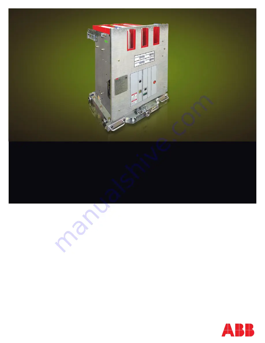
SafeGear
®
Motor Control Center
Controller
Installation, Operation and Maintenance Manual
2017
Page 1: ...SafeGear Motor Control Center Controller Installation Operation and Maintenance Manual 2017...
Page 2: ......
Page 3: ...Safe Practices 2 3 Receiving Handling and Storage 3 4 General overview 4 5 Normal Service Conditions 4 6 Construction 5 7 Extraction Truck Assembly 5 8 Racking System and Disconnect 6 9 Shutter s Char...
Page 4: ...tion primary contacts are separated from the bus contacts while the secondary contacts remain engaged to the controller to be tested The connection of secondary circuits shall be completely automatic...
Page 5: ...ion or maintenance of these power controllers DO NOT work on an energized controller DO NOT work on a controller unless all components are disconnected by means of a visible controller and securely gr...
Page 6: ...available for use with the SafeGear MCC controller Once removed from the shipping container the controller wheels are designed to move the controller across a clean smooth paved even surface Care mus...
Page 7: ...osphere Table 2 If the contactor is to be used in conditions other than those specified above please consult the factory Controller Weight Approximate Controller 400 A 720 A Maximum Weight approximate...
Page 8: ...to the controller itself in lieu of being inside the MCC controller cell Vacuum controller power fuses control power transformer CPT and all auxiliary contacts are mounted on a truck assembly and are...
Page 9: ...oller to be tested Interlocks The truck has three different mechanical interlocks in the controller construction 1 The first makes it impossible to rack the controller in with the door open Highlighte...
Page 10: ...conection with the primary contacts Procedure Before placing the contactor inside the module is necessary to manually charge the springs showns Steps for charging the springs manually 1 The spring is...
Page 11: ...lift truck 3 Raise platform for easy insertion of platform guides then lower lift truck until platform guides are fully engaged and hooked into MCC compartment cell 4 Pull back on lift truck to insur...
Page 12: ...CUIT CHECKOUT The preferred method to check the control circuit is to furnish a separate temporary control power source of the required control voltage rating The temporary source must have a properly...
Page 13: ...gaging the lift trucle 2 Ground Bus 3 Interference Blocking Plate 4 Secondary Disconnects 5 Wheel Rails 6 Shutter 7 TOC Switch Fig 4 Basic Cell 6 7 2 5 1 4 3 SafeGear Motor Control Center Controller I...
Page 14: ...t need to be inspected and lubricated Apply grease Moykote 33 to entire racking screw pin and bushing surfaces Inspect the position Release Shaft 3 cell locking tabs 7 and secondary Locking Tab 1 for...
Page 15: ...ally operated using controls in the MCC or electrically charged after manual operation of the controller in a MCC aisle Test Cabinet A test cabinet is a wall mounted control cabinet connected to a sep...
Page 16: ...tatus 6 Local Trip 7 Collar 8 Racking Screw 9 Position Release Lever 10 Insertion Removal Handle 11 Cell Interlock Tab 12 Truck 13 Wheel 14 CPT 15 Shutter s Charge Mechanism 16 Fuse Box 2 3 7 8 9 10 1...
Page 17: ...Appendix B Basic Controller Dimensions DRAWOUT 400 A CONTROLLER DRAWOUT 720 A CONTROLLER SafeGear Motor Control Center Controller Installation Operation and Maintenance Manual 14...
Page 18: ...owntime of the equipment continues to rise What happens with a phase loss When a 3 phase motor runs with one phase missing the remaining 2 phases will take more load from the missing phase making them...
Page 19: ...uld be electrically disconnected by means of a visible break securely grounded locked out and tagged in accordance with personnel precautions spelled out in ANSI ASSE Z244 1 Control of Hazardous Energ...
Page 20: ...the blow fuse mechanism for a 720 A controller 1 Remove the plastic bolts on the cover that supports the blown fuse switch 1 Remove the blown fuse mechanism 3 4 17 SafeGear Motor Control Center Contro...
Page 21: ...4 bolts that fix the fuse 1 Extract the insulation barrier between the fuses 1 The failed power fuse can be removed 5 6 7 SafeGear Motor Control Center Controller Installation Operation and Maintenan...
Page 22: ...the same size 1 Tighten the 4 bolts which fix the fuse with a torque of 13 pound foot lb ft 1 Reinsert the insulation barrier between the fuses 8 9 10 19 SafeGear Motor Control Center Controller Inst...
Page 23: ...wn fuse mechanism just as mentioned in point 2 and verify its right operation 1 The fuse replacement is complete 11 12 13 1 Tighten the plastic bolts on the cover that supports the blown fuse switch S...
Page 24: ...time with terminals 3 4 jumpered and switching power on and off to terminals 1 2 is between 280 320 ms The HCV 5HA opening time with terminals 1 2 continuously powered and switching opening contacts c...
Page 25: ...ss energy A button in front of the controller Fig 1 is used for manual trip manually when deenergized The trip mechanism is located on the contoller compartment door Fig 2 This is an optional feature...
Page 26: ...the silicon varnish Check the main contact wear in the vacuum interrupter If the wear gauge can be inserted then there is sufficient contact material available for continued use If the gauge cannot b...
Page 27: ...carried out in a manner of ways depending upon material of product Below is thecrecommended method of disposal for various raw materials ABB is committed to complying with the relevant legal and othe...
Page 28: ...ion products services or related graphics contained in the document for any purpose Any reliance placed on such information is therefore strictly at your own risk ABB reserves the right to discontinue...