


5 Diaphragm seal models
5.1 Wafer Remote Seal (S26WA and S26WE)
The wafer remote seal is designed to be clamped between
two ASME (S26WA) or EN raised face flanges (S26WE). The
diaphragm side of the seal faces the process flange and a
back-up flange is used on the other side of the seal. The
S26WA wafer seals can be used with: ANSI CL150, CL300,
CL600, CL900 or CL1500 flanges whereas the S26WE with
EN DN 10-40, DN64-160.
For mounting dimensions for the wafer remote seal are listed
in this chapter. The required back-up flange can be supplied
by the user, or it can be obtained as an option with the seal
system. Bolts, nuts, and a flange gasket must be supplied by
the user.
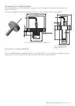
Note.
In case of DP style transmitter with one remote seal, please
refer to “Liquid Level Measurement” Section.
Model S26WA (manufactured according to ASME B16.5) is
characterized by a maximum working pressure up to
41.37 MPa (413.7 bar or 6000 psi). Model S26WE
(manufactured according to EN 1092-1) can have different
pressure limits because of the relevant forms:
— Form B1 up to 40 MPa (400 bar or 5800 psi)
— Form D up to 16 MPa (160 bar or 2320 psi)
— Form E up to 10 MPa (100 bar or 1450 psi)
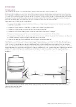
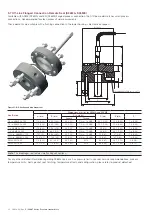
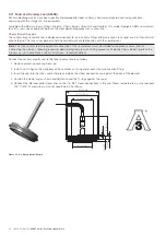
Figure 14: Wafer / Pancake style remote seal
Connect the seal element as follows:
1. Remove protective covering from seal.
2. Install a gasket between the flange and the seal surface.
3. Clamp the seal between two flanges (see Figure 12). Be
sure that the gasket is properly positioned between the
process flange and the seal element gasket surface.
4. Tighten bolts firmly and uniformly in accordance with
standard industrial flange bolting practices.
For vacuum service recommendations, temperature limits,
gasket finish, temperature effects and configuration, please
refer to product datasheet.
Ø D
Ø A flushing ring
134 (5.3)
25 (0.98) for 1/4 NPT
33 (1.30) for 1/2 NPT
M6
Ø C
Ø B
4 (0.16)
20 (0.79)
M6
Ø D
134 (5.3)
Ø diaphragm
Ø D
Ø B
24 (0.98)
4.5 (0.18)
M6
134 (5.3)
Ø diaphragm
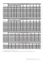
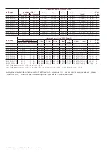
Dimensions mm (in) for S26W
Size/Rating
diaphragm (dia)
A flushing ring
internal dia
B (dia)
C (dia)
D (dia)
std. thickness
low thickness
1 1/2 in. ASME B16.5
47 (1.85)
47 (1.85)
52 (2.05)
NA
NA
73 (2.87)
2 in. ASME B16.5
60 (2.36)
58 (2.28)
62 (2.44)
NA
NA
92 (3.62)
3 in. ASME B16.5
89 (3.5)
75 (2.95)
92 (3.62)
NA
NA
127 (5)
DN 40 EN 1092-1 Form B1
47 (1.85)
47 (1.85)
52 (2.05)
NA
NA
88 (3.46)
DN 50 EN 1092-1 Form B1
60 (2.36)
58 (2.28)
62 (2.44)
NA
NA
102 (4.02)
DN 80 EN 1092-1 Form B1
89 (3.5)
75 (2.95)
92 (3.62)
NA
NA
138 (5.43)
DN 40 EN 1092-1 Form D
47 (1.85)
47 (1.85)
NA
60 (2.36)
76 (2.99)
88 (3.46)
DN 50 EN 1092-1 Form D
60 (2.36)
58 (2.28)
NA
72 (2.83)
88 (3.46)
102 (4.02)
DN 80 EN 1092-1 Form D
89 (3.5)
75 (2.95)
NA
105 (4.13)
121 (4.76)
138 (5.43)
DN 40 EN 1092-1 Form E
47 (1.85)
47 (1.85)
NA
75 (2.95)
NA
88 (3.46)
DN 50 EN 1092-1 Form E
60 (2.36)
58 (2.28)
NA
87 (3.42)
NA
102 (4.02)
DN 80 EN 1092-1 Form E
89 (3.5)
75 (2.95)
NA
120 (4.72)
NA
138 (5.43)
20 (0.78)
M6
Gasket seat
Ø diaphagm
ASME and EN 1092-1 Form B1 smooth and serrated
EN 1092-1 Form D
EN 1092-1 Form E
14 OI/S26-EN Rev. B
| 2600T Series Pressure transmitters


