


Installation
18
RHD250 ... 4000 42/68-165-EN
Pos: 8.26 /Überschriften/1.1/1-spaltig/M - O/Maßzeichnungen @ 11\mod_1157707121639_3101.doc @ 40791
3.6
Dimensioned drawings
Pos: 8.27 /Überschriften/1.1.1/1-spaltig/Hebeltrieb RHD250 @ 14\mod_1194260761218_3101.doc @ 135777
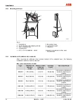
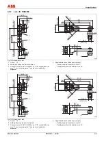
3.6.1 Lever for RHD250
Pos: 8.28 /Technische Daten / Datenblatt/Aktorik/Antriebe/Schwenkantriebe/El. Schwenkantrieb RHD 250 (Contrac)/Maßbild Hebeltrieb @ 5\mod_1152865563125_3101.doc @ 34924
4
1
2
3
M00112
265
50
16
5
21
50
- 0,051
45
- 0,015
150
40
120
8
33,3
+0,2
60
30
+
0,033
0,000
200
40
Ø18
30
74
18
23
100
...
120
L-220
L
18
100
...
120
23
99
19
Fig. 6: Dimensions in mm
1 Cone 1 : 10
2 Welding bushings are part of shipment
3 Connection pipe 1 1/4” DIN 2440 resp. 1 1/4” schedule 80 pipe
size “L” acc. to requirements. The pipe is not included in
shipment.
4 Angular deflection of ball and socket joint:
Pointing towards the actuator: max. 3°
Pointing away from the actuator: max. 10°


