


RG M4 0 M ETE R QU I CK STA RT G U I DE
Installation of the RGM40 meter must be
performed only by qualified personnel who
follow standard safety precautions during all
procedures. Those personnel should have
appropriate training and experience with high
voltage devices. Appropriate safety gloves,
safety glasses and protective clothing are
recommended.
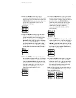
During normal operation of the RGM40 meter,
dangerous voltages flow through many parts of
the unit, including: Terminals and any connected
CTs (current transformers) and PTs (potential
transformers), all I/O modules and their circuits.
All primary and secondary circuits can, at times,
produce lethal voltages and currents. Avoid
contact with any current-carrying surfaces.
Do not use the meter or any I/O device for
primary protection or in an energy-limiting
capacity. The meter can only be used as
secondary protection.
IMPORTANT! Refer to your meter’s user
manual for additional safety warnings before
performing installation, wiring or maintenance
of your meter.
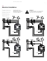
1. Slide top groove of meter
onto the DIN rail.
2. Press gently until the meter
clicks into place.
3. Use two screws to secure
the meter to the DIN rail.
—
01
—
01 DIN mount
Din mount
mount din
Mount DIN
—
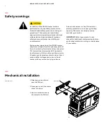
Safety warnings
—
Mechanical installation
2


