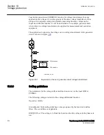
does not provide any guidance in finding the faulted component. Therefore,
ROV2PTOV (59N) is often used as a backup protection or as a release signal for the
feeder ground fault protection.
10.3.3
Setting guidelines
M13853-3 v8
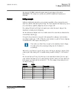
All the voltage conditions in the system where ROV2PTOV (59N) performs its
functions should be considered. The same also applies to the associated equipment, its
voltage withstand capability and time characteristic.
All voltage-related settings are made as a percentage of a settable base voltage, which
shall be set to the primary nominal voltage (phase-phase) level of the power system or
the high-voltage equipment under consideration.
The time delay for ROV2PTOV (59N) is seldom critical, since residual voltage is
related to ground faults in a high-impedance grounded system, and enough time must
normally be given for the primary protection to clear the fault. In some more specific
situations, where the residual overvoltage protection is used to protect some specific
equipment, the time delay is shorter.
Some applications and related setting guidelines for the residual voltage level are given
below.
10.3.3.1
Equipment protection, such as for motors, generators, reactors and
transformersEquipment protection for transformers
M13853-9 v8
High residual voltage indicates ground fault in the system, perhaps in the component to
which two step residual overvoltage protection (ROV2PTOV, 59N) is connected. For
selectivity reasons to the primary protection for the faulted device, ROV2PTOV (59N)
must trip the component with some time delay. The setting must be above the highest
occurring "normal" residual voltage and below the highest acceptable residual voltage
for the equipment.
10.3.3.2
Equipment protection, capacitors
M13853-12 v4
High voltage will deteriorate the dielectric and the insulation. Two step residual
overvoltage protection (ROV2PTOV, 59N) has to be connected to a neutral or open
delta winding. The setting must be above the highest occurring "normal" residual
voltage and below the highest acceptable residual voltage for the capacitor.
Section 10
1MRK 504 163-UUS A
Voltage protection
622
Transformer protection RET670 2.2 ANSI
Application manual
Summary of Contents for RELION RET670
Page 1: ...RELION 670 SERIES Transformer protection RET670 Version 2 2 ANSI Application manual ...
Page 2: ......
Page 48: ...42 ...
Page 64: ...58 ...
Page 74: ...68 ...
Page 104: ...98 ...
Page 194: ...188 ...
Page 518: ...512 ...
Page 618: ...612 ...
Page 648: ...642 ...
Page 666: ...660 ...
Page 672: ...666 ...
Page 682: ...676 ...
Page 844: ...838 ...
Page 868: ...862 ...
Page 956: ...950 ...
Page 964: ...958 ...
Page 1004: ...998 ...
Page 1014: ...1008 ...
Page 1015: ...1009 ...


