Keysight Technologies AC6800 Series, Operating And Service Manual
The Keysight Technologies AC6800 Series Operating and Service Manual is available for free download on our website. This essential manual provides detailed instructions for operating and maintaining your AC6800 Series product. Access the manual today for comprehensive guidance on maximizing the performance of your device.
Share
Download


Reviews:
No comments
Related manuals for AC6800 Series

DP1E2663030MT
Brand: nVent Hoffman Pages: 4

Liebert MPX Elementary
Brand: Emerson Pages: 16
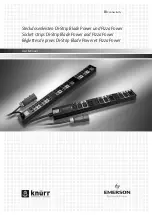
Di-Strip
Brand: Emerson Pages: 20
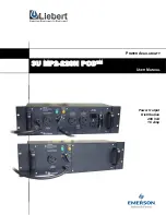
3U MP2-220N POD
Brand: Emerson Pages: 18

Liebert MicroPOD MP2-210K
Brand: Emerson Pages: 16

MPHR2204
Brand: Emerson Pages: 51

Liebert PPC 15-30 kVA
Brand: Emerson Pages: 24

Network Poewr MPH2
Brand: Emerson Pages: 36

Avocent PM 3000
Brand: Emerson Pages: 66

GreenPower
Brand: Monster Power Pages: 11

HP-1000-G14C
Brand: High Power Pages: 29

Expert Power Control 8291
Brand: GÜDE Pages: 91

Expert Power Control 8031 Series
Brand: GÜDE Pages: 98

Expert Power Control 8041 Series
Brand: GÜDE Pages: 118

Expert Power Control 8221 Series
Brand: GÜDE Pages: 115

POS GUARDIAN
Brand: SmartPower Pages: 4

SafeRing
Brand: ABB Pages: 24

PowerWorx Select Series
Brand: ADC Pages: 32


