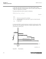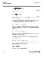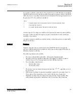
Mode
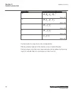
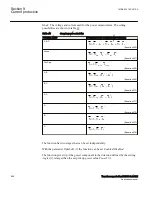
: The voltage and current used for the power measurement. The setting
possibilities are shown in table
.
Table 45:
Complex power calculation
Set value
Mode
Formula used for complex power calculation
A,B,C
*
*
*
A
B
C
A
B
C
S V
I
V
I
V
I
=
×
+
×
+
×
EQUATION2038 V1 EN-US
(Equation 466)
Arone
*
*
A
C
AB
BC
S V
I
V
I
=
×
×
-
EQUATION2039 V1 EN-US
(Equation 467)
PosSeq
*
PosSeq
PosSeq
S 3 V
I
= ×
×
EQUATION2040 V1 EN-US
(Equation 468)
A,B
*
A
B
AB
*
S
V
(I
I
)
=
×
-
EQUATION2041 V1 EN-US
(Equation 469)
B,C
*
B
C
BC
*
S
V
(I
I
)
=
×
-
EQUATION2042 V1 EN-US
(Equation 470)
C,A
*
C
A
CA
*
S
V
(I
I
)
=
×
-
EQUATION2043 V1 EN-US
(Equation 471)
A
*
A
A
S 3 V
I
= ×
×
EQUATION2044 V1 EN-US
(Equation 472)
B
*
B
B
S 3 V
I
= ×
×
EQUATION2045 V1 EN-US
(Equation 473)
C
*
C
C
S 3 V
I
= ×
×
EQUATION2046 V1 EN-US
(Equation 474)
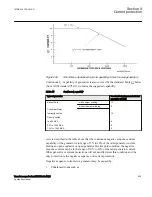
The function has two stages that can be set independently.
With the parameter
OpMode1(2)
the function can be set
Enabled
/
Disabled
.
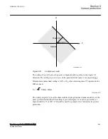
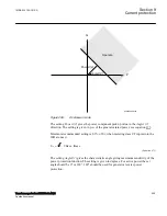
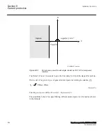
The function gives trip if the power component in the direction defined by the setting
Angle1(2)
is larger than the set pick up power value
Power1(2)
Section 9
1MRK 504 163-UUS A
Current protection
588
Transformer protection RET670 2.2 ANSI
Application manual
Summary of Contents for RELION RET670
Page 1: ...RELION 670 SERIES Transformer protection RET670 Version 2 2 ANSI Application manual ...
Page 2: ......
Page 48: ...42 ...
Page 64: ...58 ...
Page 74: ...68 ...
Page 104: ...98 ...
Page 194: ...188 ...
Page 518: ...512 ...
Page 618: ...612 ...
Page 648: ...642 ...
Page 666: ...660 ...
Page 672: ...666 ...
Page 682: ...676 ...
Page 844: ...838 ...
Page 868: ...862 ...
Page 956: ...950 ...
Page 964: ...958 ...
Page 1004: ...998 ...
Page 1014: ...1008 ...
Page 1015: ...1009 ...

