=
C
C
Line
X
K
X
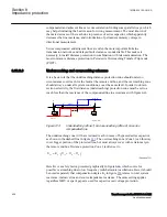
EQUATION1895 V1 EN-US
(Equation 328)
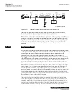
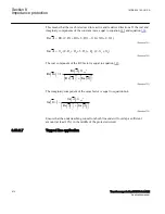
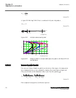
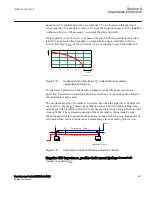
A typical 500 km long 500 kV line is considered with source impedance
1
0
=
SA
Z
EQUATION1896 V1 EN-US
(Equation 329)
~
E
A
Z
SA1
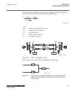
Power line
A
B
Seires
capacitor
Load
en06000585.vsd
IEC06000585 V1 EN-US
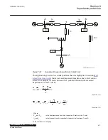
Figure 199:
A simple radial power system
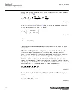
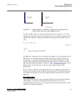
en06000586_ansi.vsd
0
200
400
600
800
1000
1200
1400
1600
1800
100
200
300
400
500
P[MW]
V
[k
V
]
V
limit
P
0
P
3
0
P
5
0
P
7
0
ANSI06000586 V1 EN-US
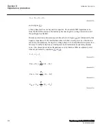
Figure 200:
Voltage profile for a simple radial power line with 0, 30, 50 and 70% of
compensation
8.13.3.2
Increase in power transfer
GUID-C9163D4E-CC2B-4645-B2AC-2C8A3FE3D337 v3
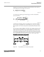
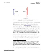
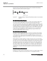
The increase in power transfer capability as a function of the degree of compensation
for a transmission line can be explained by studying the circuit shown in figure
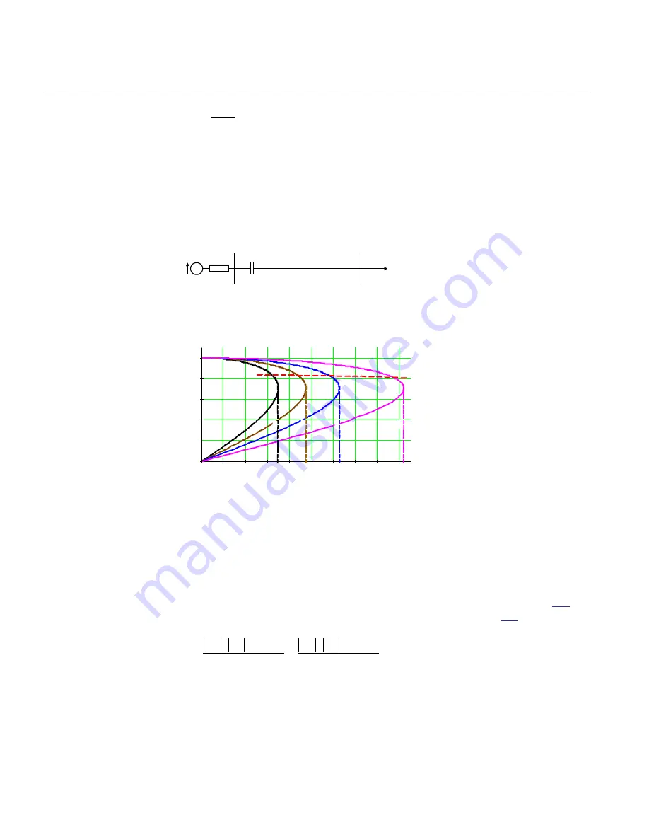
The power transfer on the transmission line is given by the equation
( )
( )
(
)
A
B
A
B
Line
C
Line
C
V
V
sin
V
V
sin
P
X
X
X
1 K
d
d
×
×
×
×
=
=
-
× -
EQUATION1994-ANSI V1 EN-US
(Equation 330)
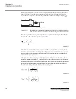
The compensation degree K
c
is defined as equation
Section 8
1MRK 504 163-UUS A
Impedance protection
414
Transformer protection RET670 2.2 ANSI
Application manual
Summary of Contents for RELION RET670
Page 1: ...RELION 670 SERIES Transformer protection RET670 Version 2 2 ANSI Application manual ...
Page 2: ......
Page 48: ...42 ...
Page 64: ...58 ...
Page 74: ...68 ...
Page 104: ...98 ...
Page 194: ...188 ...
Page 518: ...512 ...
Page 618: ...612 ...
Page 648: ...642 ...
Page 666: ...660 ...
Page 672: ...666 ...
Page 682: ...676 ...
Page 844: ...838 ...
Page 868: ...862 ...
Page 956: ...950 ...
Page 964: ...958 ...
Page 1004: ...998 ...
Page 1014: ...1008 ...
Page 1015: ...1009 ...

