Parallel line applications
GUID-9980E92C-EDB1-4E0C-A4BD-167C896199A1 v1
This type of networks are defined as those networks where the parallel transmission
lines terminate at common nodes at both ends.
The three most common operation modes are:
1. parallel line in service.
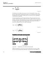
2. parallel line out of service and grounded.
3. parallel line out of service and not grounded.
Parallel line in service
GUID-F792E7FD-2265-4250-9026-1F03039FB0B5 v1
This type of application is very common and applies to all normal sub-transmission
and transmission networks.
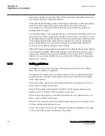
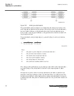
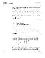
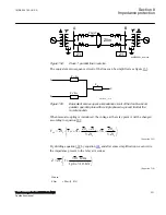
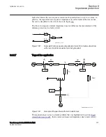
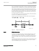
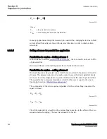
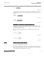
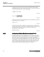
Let us analyze what happens when a fault occurs on the parallel line see figure
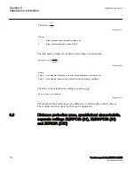
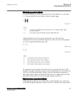
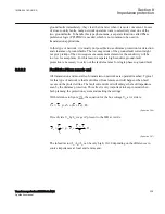
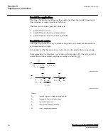
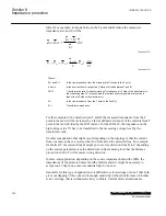
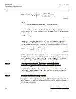
From symmetrical components, we can derive the impedance Z at the relay point for
normal lines without mutual coupling according to equation
.
ph
ph
0
1
ph
0
N
ph
0
1
U
U
Z
Z
I
3I K
I
3I
3 Z
Z
=
=
-
+
×
+
×
×
EQUATION2311 V1 EN-US
(Equation 208)
ph
ph
0
1
ph
N
ph
0
1
0
V
V
Z
Z
I
3
K
I
3I
3 Z
I
Z
=
=
-
+
×
+
×
×
EQUATION1275 V3 EN-US
(Equation 208)
Where:
V
ph
is phase to ground voltage at the relay point
I
ph
is phase current in the faulty phase
3I
0
is ground fault current
Z
1
is positive sequence impedance
Z
0
is zero sequence impedance
Section 8
1MRK 504 163-UUS A
Impedance protection
330
Transformer protection RET670 2.2 ANSI
Application manual
Summary of Contents for RELION RET670
Page 1: ...RELION 670 SERIES Transformer protection RET670 Version 2 2 ANSI Application manual ...
Page 2: ......
Page 48: ...42 ...
Page 64: ...58 ...
Page 74: ...68 ...
Page 104: ...98 ...
Page 194: ...188 ...
Page 518: ...512 ...
Page 618: ...612 ...
Page 648: ...642 ...
Page 666: ...660 ...
Page 672: ...666 ...
Page 682: ...676 ...
Page 844: ...838 ...
Page 868: ...862 ...
Page 956: ...950 ...
Page 964: ...958 ...
Page 1004: ...998 ...
Page 1014: ...1008 ...
Page 1015: ...1009 ...

