en06000586_ansi.vsd
0
200
400
600
800
1000
1200
1400
1600
1800
100
200
300
400
500
P[MW]
V
[k
V
]
V
limit
P
0
P
3
0
P
5
0
P
7
0
ANSI06000586 V1 EN-US
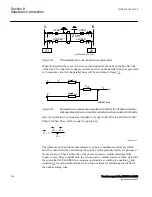
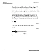
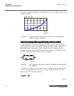
Figure 80:
Voltage profile for a simple radial power line with 0, 30, 50 and 70% of
compensation
Increased power transfer capability by raising the first swing stability limit
SEMOD168320-32 v2
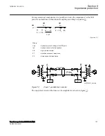
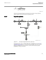
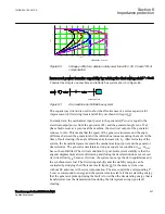
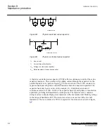
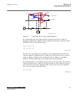
Consider the simple one-machine and infinite bus system shown in figure
en06000587.vsd
~
E
A
Z
SA1
A
B
P
Mech
+jX
Line
-jX
C
System
IEC06000587 V1 EN-US
Figure 81:
One machine and infinite bus system
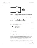
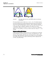
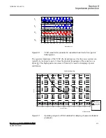
The equal-areas criterion is used to show the effectiveness of a series capacitor for
improvement of first swing transient stability (as shown in figure
).
In steady state, the mechanical input power to the generator (P
Mech
) is equal to the
electrical output power from the generator (P
E
) and the generator angle is
d
0
. If a 3-
phase fault occurs at a point near the machine, the electrical output of the generator
reduces to zero. This means that the speed of the generator increases and the angle
difference between the generator and the infinite bus increases during the fault. At the
time of fault clearing, the angle difference has increased to δ
C
. After reclosing of the
system, the transmitted power exceeds the mechanical input power and the generator
deaccelerates. The generator decelerates as long as equal area condition A
ACC
=A
DEC
has not been fulfilled. The critical condition for post-fault system stability is that the
angular displacement after fault clearing and during the deceleration does not exceed
its critical limit δ
CR
, because if it does, the system cannot get back to equilibrium and
the synchronism is lost. The first swing stability and the stability margin can be
evaluated by studying the different areas in figure
for the same system, once
without SC and once with series compensation. The areas under the corresponding P –
δ curves correspond to energy and the system remains stable if the accelerating energy
that the generator picks up during the fault is lower than the decelerating energy that is
transferred across the transmission line during the first system swing upon fault
clearing.
1MRK 504 163-UUS A
Section 8
Impedance protection
Transformer protection RET670 2.2 ANSI
207
Application manual
Summary of Contents for RELION RET670
Page 1: ...RELION 670 SERIES Transformer protection RET670 Version 2 2 ANSI Application manual ...
Page 2: ......
Page 48: ...42 ...
Page 64: ...58 ...
Page 74: ...68 ...
Page 104: ...98 ...
Page 194: ...188 ...
Page 518: ...512 ...
Page 618: ...612 ...
Page 648: ...642 ...
Page 666: ...660 ...
Page 672: ...666 ...
Page 682: ...676 ...
Page 844: ...838 ...
Page 868: ...862 ...
Page 956: ...950 ...
Page 964: ...958 ...
Page 1004: ...998 ...
Page 1014: ...1008 ...
Page 1015: ...1009 ...

