background image

10.7.2 

Application

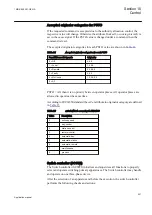
Selector mini switch (VSGGIO) function is a multipurpose function used in the
configuration tool in PCM600 for a variety of applications, as a general purpose
switch. VSGGIO can be used for both acquiring an external switch position (through
the IPOS1 and the IPOS2 inputs) and represent it through the single line diagram
symbols (or use it in the configuration through the outputs POS1 and POS2) as well
as, a command function (controlled by the PSTO input), giving switching commands
through the CMDPOS12 and CMDPOS21 outputs.

The output POSITION is an integer output, showing the actual position as an integer
number 0 – 3.

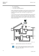
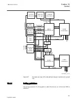
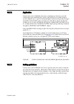
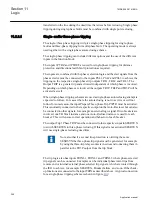
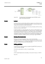
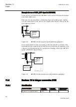
An example where VSGGIO is configured to switch Autorecloser on–off from a
button symbol on the local HMI is shown in 

figure 98

The I and O buttons on the local

HMI are normally used for on–off operations of the circuit breaker.

IEC07000112-2-en.vsd

PSTO

CMDPOS12

IPOS1

NAM_POS1
NAM_POS2

IPOS2

CMDPOS21

OFF

ON

VSGGIO

SMBRREC

ON
OFF

SETON

INTONE

INVERTER

INPUT

OUT

IEC07000112 V2 EN

Figure 98:

Control of Autorecloser from local HMI through Selector mini switch

10.7.3 

Setting guidelines

Selector mini switch (VSGGIO) function can generate pulsed or steady commands
(by setting the 

Mode

 parameter). When pulsed commands are generated, the length of

the pulse can be set using the 

tPulse

 parameter. Also, being accessible on the single

line diagram (SLD), this function block has two control modes (settable through

CtlModel

): 

Dir Norm

 and 

SBO Enh

.

1MRK 505 291-UEN A

Section 10

Control

241

Application manual

Summary of Contents for Relion REQ650

Page 1: ...Relion 650 series Breaker protection REQ650 Application manual ...

Page 2: ......

Page 3: ...Document ID 1MRK 505 291 UEN Issued October 2016 Revision A Product version 1 3 Copyright 2013 ABB All rights reserved ...

Page 4: ...SL Project for use in the OpenSSL Toolkit http www openssl org This product includes cryptographic software written developed by Eric Young eay cryptsoft com and Tim Hudson tjh cryptsoft com Trademarks ABB and Relion are registered trademarks of the ABB Group All other brand or product names mentioned in this document may be trademarks or registered trademarks of their respective holders Warranty ...

Page 5: ...product failure would create a risk for harm to property or persons including but not limited to personal injuries or death shall be the sole responsibility of the person or entity applying the equipment and those so responsible are hereby requested to ensure that all measures are taken to exclude or mitigate such risks This document has been carefully checked by ABB but deviations cannot be compl...

Page 6: ...erning electrical equipment for use within specified voltage limits Low voltage directive 2006 95 EC This conformity is the result of tests conducted by ABB in accordance with the product standards EN 50263 and EN 60255 26 for the EMC directive and with the product standards EN 60255 1 and EN 60255 27 for the low voltage directive The product is designed in accordance with the international standa...

Page 7: ...yard 32 Line bay in a high impedance earthed network connected to single busbar switchyard 33 Line bay in a solidly earthed network connected to double busbar switchyard 34 Line bay in a high impedance earthed network connected to double busbar switchyard 35 Functionality table 35 Transformer bay in a solidly earthed network connected to single busbar switchyard 38 Transformer bay in a solidly ear...

Page 8: ...aker failure protection 3 phase activation and output CCRBRF 58 Calculating settings for pole discordance protection CCRPLD 59 Section 4 Analog inputs 61 Introduction 61 Setting guidelines 61 Setting of the phase reference channel 61 Relationships between setting parameter Base Current CT rated primary current and minimum pickup of a protection IED 62 Setting of current channels 62 Example 1 63 Ex...

Page 9: ...hase segregated output SPTPIOC 90 Identification 90 Application 90 Setting guidelines 90 Meshed network without parallel line 91 Meshed network with parallel line 93 Four step phase overcurrent protection 3 phase output OC4PTOC 94 Identification 94 Application 94 Setting guidelines 95 Settings for steps 1 to 4 97 2nd harmonic restrain 98 Four step phase overcurrent protection phase segregated outp...

Page 10: ...lines 132 Breaker failure protection 3 phase activation and output CCRBRF 133 Identification 133 Application 133 Setting guidelines 134 Breaker failure protection phase segregated activation and output CSPRBRF 136 Identification 136 Application 136 Setting guidelines 137 Stub protection STBPTOC 140 Identification 140 Application 140 Setting guidelines 140 Pole discordance protection CCRPLD 141 Ide...

Page 11: ...ystem faults 156 Settings for Two step undervoltage protection 157 Two step overvoltage protection OV2PTOV 158 Identification 158 Application 158 Setting guidelines 159 Two step residual overvoltage protection ROV2PTOV 161 Identification 161 Application 161 Setting guidelines 162 Power supply quality 162 High impedance earthed systems 162 Direct earthed system 163 Settings for Two step residual ov...

Page 12: ...ased 177 Delta U and delta I 177 Dead line detection 178 Breaker close trip circuit monitoring TCSSCBR 178 Identification 178 Application 179 Section 10 Control 183 Synchrocheck energizing check and synchronizing SESRSYN 183 Identification 183 Application 183 Synchronizing 183 Synchrocheck 184 Energizing check 186 Voltage selection 187 External fuse failure 188 Application examples 189 Single circ...

Page 13: ...04 Configuration 204 Auto recloser parameter settings 208 Autorecloser for 1 3 phase operation STBRREC 211 Identification 211 Application 211 Auto reclosing operation Off and On 215 Start auto reclosing and conditions for start of a reclosing cycle 215 Start auto reclosing from CB open information 215 Blocking of the autorecloser 216 Control of the auto reclosing open time for shot 1 216 Long trip...

Page 14: ... earthing switch BB_ES 238 Interlocking for bus section breaker A1A2_BS 239 Interlocking for bus section disconnector A1A2_DC 239 Interlocking for bus coupler bay ABC_BC 239 Interlocking for 1 1 2 CB BH 239 Interlocking for double CB bay DB 239 Interlocking for line bay ABC_LINE 239 Interlocking for transformer bay AB_TRAFO 239 Logic rotating switch for function selection and LHMI presentation SLG...

Page 15: ... 249 Blocking of the function block 249 Setting guidelines 249 Trip matrix logic TMAGGIO 250 Identification 250 Application 250 Setting guidelines 250 Configurable logic blocks 251 Identification 251 Application 252 Configuration 252 Fixed signals FXDSIGN 253 Identification 253 Application 253 Boolean 16 to integer conversion B16I 254 Identification 254 Application 255 Setting guidelines 255 Boole...

Page 16: ...ation I O functions 16 inputs SP16GGIO 259 Identification 259 Application 259 Setting guidelines 260 IEC61850 generic communication I O functions MVGGIO 260 Identification 260 Application 260 Setting guidelines 260 Measurements 261 Identification 261 Application 261 Setting guidelines 263 Setting examples 266 Measurement function application for a 110kV OHL 266 Event counter CNTGGIO 269 Identifica...

Page 17: ...ing SSCBR 278 Identification 278 Application 279 Section 13 Metering 283 Pulse counter PCGGIO 283 Identification 283 Application 283 Setting guidelines 283 Energy calculation and demand handling EPTMMTR 284 Identification 284 Application 284 Setting guidelines 285 Section 14 Station communication 287 IEC61850 8 1 communication protocol 287 Identification 287 Application 287 Horizontal communicatio...

Page 18: ...uidelines 304 IED identifiers TERMINALID 304 Identification 304 Application 304 Customer specific settings 304 Product information PRODINF 304 Identification 304 Application 305 Factory defined settings 305 Primary system values PRIMVAL 306 Identification 306 Application 306 Signal matrix for analog inputs SMAI 306 Identification 306 Application 306 Setting guidelines 307 Summation block 3 phase 3...

Page 19: ...rotection 318 Non directional instantaneous and definitive time phase and residual overcurrent protection 318 Non directional inverse time delayed phase and residual overcurrent protection 319 Directional phase and residual overcurrent protection 320 Current transformer requirements for CTs according to other standards 320 Current transformers according to IEC 61869 2 class P PR321 Current transfo...

Page 20: ...14 ...

Page 21: ... manual can also provides assistance for calculating settings 1 2 Intended audience This manual addresses the protection and control engineer responsible for planning pre engineering and engineering The protection and control engineer must be experienced in electrical power engineering and have knowledge of related technology such as protection schemes and communication principles 1MRK 505 291 UEN...

Page 22: ...of protection and control functions LHMI functions as well as communication engineering for IEC 60870 5 103 IEC 61850 and DNP 3 0 The installation manual contains instructions on how to install the IED The manual provides procedures for mechanical and electrical installation The chapters are organized in the chronological order in which the IED should be installed The commissioning manual contains...

Page 23: ... reference during the engineering phase installation and commissioning phase and during normal service The communication protocol manual describes the communication protocols supported by the IED The manual concentrates on the vendor specific implementations The point list manual describes the outlook and properties of the data points specific to the IED The manual should be used in conjunction wi...

Page 24: ... icon indicates important information or warning related to the concept discussed in the text It might indicate the presence of a hazard which could result in corruption of software or damage to equipment or property The information icon alerts the reader of important facts and conditions The tip icon indicates advice on for example how to design your project or how to use a certain function Altho...

Page 25: ...o save the changes in non volatile memory select Yes and press Parameter names are shown in italics For example the function can be enabled and disabled with the Operation setting Each function block symbol shows the available input output signal the character in front of an input output signal name indicates that the signal name may be customized using the PCM600 software the character after an i...

Page 26: ...20 ...

Page 27: ...n protection with redundant protection and control functions Three configured packages have been defined for the following applications A01 Backup protection functions in a single busbar single breaker bay with three phase trip A11 Backup protection functions in a single busbar single breaker bay with single phase trip B11 Backup protection functions in a double busbar single breaker bay with sing...

Page 28: ... Meter CC RPLD 52PD DRP RDRE Mont V MMXU Meter IEC61850 ANSI IEC Function Enabled in Settings IEC61850 ANSI IEC Function Disabled in Settings 132 kV Bus 1000 1 132kV 110V 132kV 110V OC4 PTOC 51 67 3I IEC10000321 3 en vsd SDE PSDE 67N IN LC PTTR 26 BRC PTOC 46 Iub SDD RFUF 60FL S SCBR Cond S SIMG 63 IEC10000321 V3 EN Figure 2 Typical application example of the REQ650 A01 used as backup protection i...

Page 29: ...D 52PD DRP RDRE Mont V MMXU Meter IEC61850 ANSI IEC Function Enabled in Settings 132 kV Bus 1000 1 132kV 110V 132kV 110V OC4S PTOC 51 67 3I IEC10000322 2 en vsd SDE PSDE 67N IN LCPTTR 26 BRC PTOC 46 Iub SDD RFUF 60FL S SCBR Cond TCS SCBR Cond TCS SCBR Cond S SIMG 63 IEC61850 ANSI IEC Function Disabled in Settings IEC10000322 V2 EN Figure 3 Typical application example of the REQ650 A11 used as back...

Page 30: ...U Meter C MSQI Meter CC RPLD 52PD V MMXU Meter OV2 PTOV 59 3U V MMXU Meter V MSQI Meter TCS SCBR Cond SPVN ZBAT Cond Other configured functions DRP RDRE Mont IEC61850 ANSI IEC Function Enabled in Settings IEC10000323 3 en vsd TCS SCBR Cond TCS SCBR Cond V MMXU Meter S SIMG 63 IEC61850 ANSI IEC Function Disabled in Settings 1000 5 IEC10000323 V3 EN Figure 4 Typical application example of the REQ650...

Page 31: ...n 0 1 1 1 1 LCPTTR 26 Thermal overload protection one time constant Celsius 0 1 1 1 1 LFPTTR 26 Thermal overload protection one time constant Fahrenheit 0 1 1 1 1 CCRBRF 50BF Breaker failure protection 3 phase activation and output 0 1 1 CSPRBRF 50BF Breaker failure protection phase segregated activation and output 0 1 1 1 STBPTOC 50STB Stub protection 0 1 1 1 1 CCRPLD 52PD Pole discordance protec...

Page 32: ...ction and LHMI presentation 15 15 15 15 VSGGIO Selector mini switch 20 20 20 20 DPGGIO IEC 61850 generic communication I O functions double point 16 16 16 16 SPC8GGIO Single point generic control 8 signals 5 5 5 5 AUTOBITS AutomationBits command function for DNP3 0 3 3 3 3 I103CMD Function commands for IEC60870 5 103 1 1 1 1 I103IEDCMD IED commands for IEC60870 5 103 1 1 1 1 I103USRCMD Function co...

Page 33: ...c blocks 40 40 40 40 AND Configurable logic blocks 280 280 280 280 SRMEMORY Configurable logic blocks 40 40 40 40 RSMEMORY Configurable logic blocks 40 40 40 40 Q T Configurable logic blocks Q T 0 1 ANDQT Configurable logic blocks Q T 0 120 ORQT Configurable logic blocks Q T 0 120 INVERTERQT Configurable logic blocks Q T 0 120 XORQT Configurable logic blocks Q T 0 40 SRMEMORYQT Configurable logic ...

Page 34: ... TM_S_P2 Function block for service values presentation of secondary analog inputs 600TRM 1 1 1 1 AM_S_P4 Function block for service values presentation of secondary analog inputs 600AIM 1 1 1 1 CNTGGIO Event counter 5 5 5 5 L4UFCNT Event counter with limit supervision 12 12 12 12 DRPRDRE Disturbance report 1 1 1 1 AnRADR Analog input signals 4 4 4 4 BnRBDR Binary input signals 6 6 6 6 SPGGIO IEC ...

Page 35: ...communication IEC 61850 or Function name ANSI Function description Breaker REQ650 REQ650 A01 3Ph 1CB 1BB REQ650 A11 1Ph 1CB 1BB REQ650 B11 1Ph 1CB 2BB Station communication IEC61850 8 1 IEC 61850 communication protocol 1 1 1 1 DNPGEN DNP3 0 communication general protocol 1 1 1 1 RS485DNP DNP3 0 for RS 485 communication protocol 1 1 1 1 CH1TCP DNP3 0 for TCP IP communication protocol 1 1 1 1 CH2TCP...

Page 36: ...ia GOOSE for interlocking 59 59 59 59 GOOSEBINRCV GOOSE binary receive 4 4 4 4 ETHFRNT ETHLAN1 GATEWAY Ethernet configuration of front port LAN1 port and gateway 1 1 1 1 ETHLAN1_AB Ethernet configuration of LAN1 port 1 PRPSTATUS System component for parallell redundancy protocol 1 CONFPROT IED Configuration Protocol 1 1 1 1 ACTIVLOG Activity logging parameters 1 1 1 1 SECALARM Component for mappin...

Page 37: ...r settings 6 ATHSTAT Authority status 1 ATHCHCK Authority check 1 AUTHMAN Authority management 1 FTPACCS FTPS access with password 1 DOSFRNT Denial of service frame rate control for front port 1 DOSLAN1 Denial of service frame rate control for LAN1A and LAN1B ports 1 DOSSCKT Denial of service socket flow control 1 2 3 REQ650 application examples 2 3 1 Adaptation to different applications REQ650 is...

Page 38: ...k connected to single busbar switchyard Application 6 Transformer bay in a solidly earthed network connected to double busbar switchyard Application 7 Transformer bay in a high impedance earthed network connected to single busbar switchyard 2 3 2 Line bay in a solidly earthed network connected to single busbar switchyard 3 3 1 REQ650 A01 A11 Line Feeder IEC10000134 1 en vsd IEC10000134 V1 EN Figur...

Page 39: ...e 6 Line bay in a high impedance earthed network REQ650 has a number of back up protection functions In addition to this three phase trip and autoreclosing is available for REQ650 A01 and single phase trip and autoreclosing is available for REQ650 A11 1MRK 505 291 UEN A Section 2 Application 33 Application manual ...

Page 40: ...6 1 en vsd IEC10000136 V1 EN Figure 7 Line bay in a solidly earthed network REQ650 has a number of back up protection functions In addition to this three phase trip and autoreclosing is available for REQ650 A01 and single phase trip and autoreclosing is available for REQ650 B11 Section 2 1MRK 505 291 UEN A Application 34 Application manual ...

Page 41: ...able for REQ650 B11 2 3 6 Functionality table The proposal for functionality choice for the different application cases are shown in table 5 The recommendations have the following meaning On It is recommended to have the function activated in the application Off It is recommended to have the function deactivated in the application Application dependent The decision to have the function activated o...

Page 42: ...endent Application dependent Off Pole discordance protection CCRPLD On On On On Broken conductor check BRCPTOC Application dependent Application dependent Application dependent Application dependent Directional underpower protection GUPPDUP Application dependent Application dependent Application dependent Application dependent Directional overpower protection GOPPDOP Application dependent Applicat...

Page 43: ...n dependent Application dependent Application dependent Autorecloser for 3 phase operation SMBRREC three phase trip A01 Application dependent Application dependent Application dependent Application dependent Autorecloser for 1 3 phase operation STBRREC three phase single phase trip A11 B11 Application dependent Application dependent Application dependent Application dependent Tripping logic common...

Page 44: ...dly earthed network connected to single busbar switchyard 3 3 3 REQ650 A01 Alt IEC10000138 1 en vsd IEC10000138 V1 EN Figure 9 Transformer bay in a solidly earthed system Section 2 1MRK 505 291 UEN A Application 38 Application manual ...

Page 45: ... earthed network connected to double busbar switchyard 3 REQ650 B11 Bus 1 Bus 2 IEC10000139 1 en vsd IEC10000139 V1 EN Figure 10 Transformer bay in a solidly earthed system 1MRK 505 291 UEN A Section 2 Application 39 Application manual ...

Page 46: ...n in table 9 The recommendations have the following meaning On It is recommended to have the function activated in the application Off It is recommended to have the function deactivated in the application Application dependent The decision to have the function activated or not is dependent on the specific conditions in each case Applications 5 7 in table 9 are according to application examples giv...

Page 47: ...PDOP Application dependent Application dependent Application dependent Negative sequence based overcurrent function DNSPTOC Application dependent Application dependent Application dependent Two step undervoltage protection UV2PTUV Off Off Off Two step overvoltage protection OV2PTOV Off Off Off Two step residual overvoltage protection ROV2PTOV Off Off Off Loss of voltage check LOVPTUV On On On Unde...

Page 48: ...42 ...

Page 49: ...A01 Line Feeder Solidly Earthed System IEC10000146 1 en vsd IEC10000146 V1 EN Figure 12 Line bay backup protection application The following data is assumed Table 10 Typical data for the line bay Item Data Line length 50 km Positive sequence impedance 0 05 j 0 35 ohm km 2 5 j17 5 ohm Zero sequence impedance 0 15 j 1 00 ohm km 7 5 j50 ohm High positive sequence source impedance j10 ohm about 1900 M...

Page 50: ...cation are described in setting examples It is recommended to keep the default values for all settings that are not described Refer to Technical manual for setting tables for each protection and control function Refer to setting guideline section in Application manual for guidelines on how to set functions that are not presented in setting examples Use parameter setting tool in PCM600 to set the I...

Page 51: ... Set CTSec1 to 1 A 1 3 Set CTPrim1 to 1000 A 1 4 Set the same values for current inputs 2 and 3 2 Set the voltage transformer inputs 2 1 Set VTSec7 to 110 V The rated secondary voltage of the VT given as phase to phase voltage 2 2 Set VTPrim6 to 143 kV The rated secondary voltage of the VT given as phase to phase voltage 2 3 Set the same values for current inputs 7 and 8 2 4 Set VTSec9 to 110 V Th...

Page 52: ...rcuits close to the substation 1 Set GlobalBaseSel to 1 The settings are made in primary values These values are given in the base settings in Global base 1 2 Set I to 600 of IBase The protection shall not overreach the line and it shall not trip for short circuits in the reverse direction A three phase short circuit at the remote line end and low source impedance gives the following fault current...

Page 53: ...layed step used as line backup protection It should be set to assure selectivity to line protections Directional function forward is used One delayed step used as backup protection for the own busbar It should be set to assure selectivity to line protections Directional function reverse is used A long time delayed step covering further parts of the system This step should have a time delay longer ...

Page 54: ...t circuit IEC10000147 1 en vsd IEC10000147 V1 EN Figure 13 Fault for step 1 setting In case of a three phase short circuit in zone 1 reach in the shortest line from the remote busbar as shown in figure 14 the current to the protection is I 1 5 kA Section 3 1MRK 505 291 UEN A REQ650 setting examples 48 Application manual ...

Page 55: ... this network 3 Set I1 to 200 of IBase 2000 A primary current 4 Set t1 to 0 4 s 3 1 5 3 Calculating settings for step 2 The protection shall be able to detect all short circuits in the own busbar A two phase short circuit in the busbar and high source impedance from the remote line end as shown in figure 15 results in the following fault current for the protection 145 3 3 3 2 6 85 2 2 10 2 5 17 5 ...

Page 56: ...0149 V1 EN Figure 15 Fault for step 2 setting In case of a three phase short circuit in zone 1 reach in the shortest line from the busbar as shown in figure 16 the current to the protection is I 1 8 kA Section 3 1MRK 505 291 UEN A REQ650 setting examples 50 Application manual ...

Page 57: ...Base 2000 A primary current 4 Set t2 to 0 4 s 3 1 5 4 Calculating settings for step 3 The phase overcurrent protection shall never trip for load current in extreme high load situations The maximum load current through the coupler bay is 750 A the same as the CT rated current corresponding to about 190 MVA The resetting ratio is 0 95 The minimum setting can be calculated 1 3 750 790 0 95 I A EQUATI...

Page 58: ...low source impedance results in the following fault current to the protection 0 Re 0 Re 0 0 Re 0 0 1 0 Re 0 3 3 3 2 ph sc m sc m prot o fault sc m Line sc Home o sc m o Line sc Home U Z Z I I Z Z Z Z Z Z Z Z EQUATION2345 V1 EN Zs0Rem is the zero sequence source impedance at the remote line end Z0 Line is the line zero sequence impedance and Zsc0 Home is the zero sequence source impedance at the lo...

Page 59: ...rotection It should be set to assure selectivity to line protection Directional function forward is used One delayed step used as backup protection of the own busbar It should be set to assure selectivity to line protection Directional function reverse is used A long time delayed step covering further parts of the system and detecting high resistive faults This step should have a time delay longer...

Page 60: ...V2 EN Figure 17 Fault for step 1 setting In case of a single phase earth fault in zone 1 reach in the shortest line from the remote busbar as shown in figure 18 the current to the protection is I0 1 1 kA Section 3 1MRK 505 291 UEN A REQ650 setting examples 54 Application manual ...

Page 61: ...time is used in this network 3 Set IN1 to 120 of IBase 1200 A primary current 4 Set t1 to 0 4 s 3 1 7 3 Calculating settings for step 2 The protection shall be able to detect all short circuits in the own busbar A single phase to earth fault as shown in figure 19 at the busbar and high source impedance from the remote line end results in the following fault current to the protection 0 3 1 3 87 I k...

Page 62: ... EN Figure 19 Fault for step 2 setting In case of a single phase earth fault in zone 1 reach in the shortest line from the remote busbar as shown in figure 20 the current to the protection is I 1 0 kA Section 3 1MRK 505 291 UEN A REQ650 setting examples 56 Application manual ...

Page 63: ...3 1 7 4 Calculating settings for step 3 The current setting should be chosen in line with normal setting principles in the system To detect high resistive faults a current setting of about 100 A will detect earth faults with a fault resistance up to about 800 Ω Proposed current setting is therefore 100 A 1 Set DirMode3 to Non directional 2 Set IN3 to 10 of IBase 100 A primary current 3 Set t3 to 1...

Page 64: ...urrents and the residual current shall be higher than the set level to detect failure to break 2 out of 4 at least two of the three phase currents and the residual current shall be higher than the set level to detect failure to break As the residual current protection is one of the protection functions to initiate the breaker failure protection the setting 1 out of 4 is chosen 4 Set IP to 50 of th...

Page 65: ...iscordance can be detected either from auxiliary breaker contact status or by current measurement 1 Set GlobalBaseSel to 1 The settings are made in primary values The values of the base primary quantities are set in Global base 1 2 Set Operation to On 3 Set tTrip to 3 s When asymmetry is detected a trip signal is activated The delay must be so long that asymmetrical faults will not cause an unwant...

Page 66: ...her than the setting 7 Set CurrUnsymLevel to 80 Pole discordance is detected if the magnitude of the lowest phase current is lower than the fraction CurrUnsymLevel of the highest phase current Section 3 1MRK 505 291 UEN A REQ650 setting examples 60 Application manual ...

Page 67: ...le information will be shown in relation to this analog input During testing and commissioning of the IED the reference channel can be changed to facilitate testing and service values reading 4 2 Setting guidelines 4 2 1 Setting of the phase reference channel All phase angles are calculated in relation to a defined reference An appropriate analog input channel is selected and used as phase referen...

Page 68: ...e protection scheme and installed on the same voltage level This will effectively make the protection scheme less sensitive however such measures are necessary in order to avoid possible problems with loss of the measurement accuracy in the IED Regardless of the applied relationship between the IBase parameter and the rated CT primary current the corresponding minimum pickup of the function on the...

Page 69: ...easured quantity is positive when flowing towards the object Set parameter CTStarPoint Correct Setting is ToObject Set parameter CTStarPoint Correct Setting is FromObject en05000456 vsd IEC05000456 V1 EN Figure 22 Internal convention of the directionality in the IED With correct setting of the primary CT direction CTStarPoint set to FromObject or ToObject a positive quantity always flows towards t...

Page 70: ... setting is ToObject IEC11000020 2 en vsd Is Is Ip Ip Ip IED IED IEC11000020 V2 EN Figure 23 Example how to set CTStarPoint parameters in the IED The figure 23 shows the most common case where the objects have their own CTs For the transformer protection the protected object is the transformer Therefore both CTStarPoint directions should be set ToObject For the line protection the protected object...

Page 71: ... just one line both line protection IED and transformer protection IED use the same CT The CT direction is set with different reference objects for the two IEDs though it is the same current from the same CT that is feeding the two IEDs With these settings the directional functions of the line protection shall be set to Forward to look towards the line 4 2 3 3 Examples on how to connect configure ...

Page 72: ...d utility practices the rated secondary current of a CT has typically one of the following values 1A 5A However in some cases the following rated secondary currents are used as well 2A 10A The IED fully supports all of these rated secondary values 4 2 3 4 Example on how to connect a star connected three phase CT set to the IED Figure 26 gives an example about the wiring of a star connected three p...

Page 73: ...CT set to the three CT inputs of the IED 2 The current inputs are located in the TRM It shall be noted that for all these current inputs the following setting values shall be entered for the example shown in figure 26 CTprim 600A CTsec 5A CTStarPoint ToObject Inside the IED only the ratio of the first two parameters is used The third parameter CTStarPoint ToObject as set in this example causes no ...

Page 74: ...y required only for IEDs installed in power plants then the setting parameters DFTReference shall be set accordingly Section SMAI in this manual provides information on adaptive frequency tracking for the signal matrix for analogue inputs SMAI 5 AI3P in the SMAI function block is a grouped signal which contains all the data about the phases L1 L2 L3 and neutral quantity in particular the data abou...

Page 75: ...prim 600A CTsec 5A CTStarPoint FromObject Inside the IED only the ratio of the first two parameters is used The third parameter as set in this example will negate the measured currents in order to ensure that the currents are measured towards the protected object within the IED 4 2 3 5 Example how to connect single phase CT to the IED Figure 28 gives an example how to connect the single phase CT t...

Page 76: ...wn in figure 28 CTprim 1000 A CTsec 1A CTStarPoint FromObject 3 shows the connection made in SMT tool which connect this CT input to the fourth input channel of the preprocessing function block 4 4 is a Preprocessing block that has the task to digitally filter the connected analog inputs and calculate values The calculated values are then available for all built in protection and control functions...

Page 77: ... defines the marking of voltage transformer terminals commonly used around the world A H1 B H2 b X2 a X1 A H1 N H2 n X2 a X1 b c A H1 N H2 dn X2 da X1 d UPri USec a en06000591 vsd IEC06000591 V1 EN Figure 29 Commonly used markings of VT terminals Where a is the symbol and terminal marking used in this document Terminals marked with a dot indicate the primary and secondary winding terminals with th...

Page 78: ...4 3 Examples on how to connect a three phase to earth connected VT to the IED Figure 30 gives an example on how to connect a three phase to earth connected VT to the IED It as well gives overview of required actions by the user in order to make this measurement available to the built in protection and control functions within the IED For correct terminal designations see the connection diagrams va...

Page 79: ...ages to three VT inputs on the IED 2 is the TRM where these three voltage inputs are located For these three voltage inputs the following setting values shall be entered VTprim 66 kV VTsec 110 V Inside the IED only the ratio of these two parameters is used It shall be noted that the ratio of the entered values exactly corresponds to ratio of one individual VT 66 66 3 110 110 3 EQUATION1903 V1 EN E...

Page 80: ...nce for sequence quantities These calculated values are then available for all built in protection and control functions within the IED which are connected to this preprocessing function block in the configuration tool For this application most of the preprocessing settings can be left to the default values However the following settings shall be set as shown here UBase 66 kV that is rated Ph Ph v...

Page 81: ...puts and calculate fundamental frequency phasors for all four input channels harmonic content for all four input channels positive negative and zero sequence quantities by using the fundamental frequency phasors for the first three input channels channel one taken as reference for sequence quantities These calculated values are then available for all built in protection and control functions withi...

Page 82: ...76 ...

Page 83: ...600 The LHMI is used for setting monitoring and controlling 5 1 1 Display The LHMI includes a graphical monochrome display with a resolution of 320 x 240 pixels The character size can vary The amount of characters and rows fitting the view depends on the character size and the view that is shown The display view is divided into four basic areas 1MRK 505 291 UEN A Section 5 Local human machine inte...

Page 84: ...actions are possible with the function buttons Each function button has a LED indication that can be used as a feedback signal for the function button control action The LED is connected to the required signal with PCM600 IEC12000025 2 en vsd IEC12000025 V2 EN Figure 34 Function button panel Section 5 1MRK 505 291 UEN A Local human machine interface 78 Application manual ...

Page 85: ...indicate three states with the colors green yellow and red The alarm texts related to each three color LED are divided into three pages There are 3 separate pages of LEDs available The 15 physical three color LEDs in one LED group can indicate 45 different signals Altogether 135 signals can be indicated since there are three LED groups The LEDs can be configured with PCM600 and the operation mode ...

Page 86: ...ser Log on 14 Enter 15 Remote Local 16 Uplink LED 17 Ethernet communication port RJ 45 18 Multipage 19 Menu 20 Clear 21 Help 22 Programmable alarm LEDs 23 Protection status LEDs 5 1 4 Local HMI functionality 5 1 4 1 Protection and alarm indication Protection indicators The protection indicator LEDs are Ready Start and Trip Section 5 1MRK 505 291 UEN A Local human machine interface 80 Application m...

Page 87: ...he start indication is latching and must be reset via communication or by pressing Flashing A flashing yellow LED has a higher priority than a steady yellow LED The IED is in test mode and protection functions are blocked The indication disappears when the IED is no longer in test mode and blocking is removed Table 13 Trip LED red LED state Description Off Normal operation On A protection function...

Page 88: ...F S sequence The activation signal is on or it is off but the indication has not been acknowledged LatchedAck S F sequence The indication has been acknowledged but the activation signal is still on 5 1 4 2 Parameter management The LHMI is used to access the IED parameters Three types of parameters can be read and written Numerical values String values Enumerated values Numerical values are present...

Page 89: ... IED front port with a crossed over cable the IED s DHCP server for the front interface assigns an IP address to the computer if DHCPServer On The default IP address for the front port is 10 1 150 3 Do not connect the IED front port to a LAN Connect only a single local PC with PCM600 to the front port 1MRK 505 291 UEN A Section 5 Local human machine interface 83 Application manual ...

Page 90: ...84 ...

Page 91: ...ost dangerous because no power can be transmitted through the fault point during fault conditions The magnitude of the fault current A high fault current indicates that the decrease of transmitted power is high The total fault clearing time The phase angles between the EMFs of the generators on both sides of the transmission line increase over the permitted stability limits if the total fault clea...

Page 92: ...e end which can cause high inrush current when connected to the network and can thus also cause the operation of the built in instantaneous overcurrent protection GlobalBaseSel Selects the global base value group used by the function to define IBase UBase and SBase IP Set operate current in of IBase 6 1 3 1 Meshed network without parallel line The following fault calculations have to be done for t...

Page 93: ...n 3 A safety margin of 5 for the maximum protection static inaccuracy and a safety margin of 5 for the maximum possible transient overreach have to be introduced An additional 20 is suggested due to the inaccuracy of the instrument transformers under transient conditions and inaccuracy in the system data The minimum primary setting Is for the instantaneous phase overcurrent protection 3 phase outp...

Page 94: ...usbars In this case the influence of the induced fault current from the faulty line line 1 to the healthy line line 2 is considered together with the two through fault currents IfA and IfB mentioned previously The maximal influence from the parallel line for the IED in figure 41 will be with a fault at the C point with the C breaker open A fault in C has to be applied and then the maximum current ...

Page 95: ... the safety margins mentioned previously the minimum setting Is for the instantaneous phase overcurrent protection 3 phase output is then Is 1 3 Imin EQUATION83 V2 EN Equation 7 The protection function can be used for the specific application only if this setting value is equal or less than the maximum phase fault current that the IED has to clear The IED setting value IP is given in percentage of...

Page 96: ...ansmitted power is high The total fault clearing time The phase angles between the Electro motive forces EMFs of the generators on both sides of the transmission line increase over the permitted stability limits if the total fault clearing time which consists of the protection operating time and the breaker opening time is too long The fault current on long transmission lines depends mostly on the...

Page 97: ...lobalBaseSel is used to select a GBASVAL function for reference of base values IP Set operate current in of IBase 6 2 3 1 Meshed network without parallel line The following fault calculations have to be done for three phase single phase to earth and two phase to earth faults With reference to figure 42 apply a fault in B and then calculate the current through fault phase current IfB The calculatio...

Page 98: ... have to be introduced An additional 20 is suggested due to the inaccuracy of the instrument transformers under transient conditions and inaccuracy in the system data The minimum primary setting Is for SPTPIOC is then s I 1 3 Imin EQ2 V1 EN Equation 10 The protection function can be used for the specific application only if this setting value is equal to or less than the maximum fault current that...

Page 99: ...her with the two through fault currents IfA and IfB mentioned previously The maximal influence from the parallel line for the IED in figure 45 will be with a fault at the C point with the C breaker open A fault in C has to be applied and then the maximum current IM seen from the IED on the healthy line this applies for single phase to earth and two phase to earth faults is calculated IEC10000278 1...

Page 100: ...n description IEC 61850 identification IEC 60617 identification ANSI IEEE C37 2 device number Four step phase overcurrent protection 3 phase output OC4PTOC 4 4 alt 3I TOC REVA V1 EN 51 67 6 3 2 Application The Four step phase overcurrent protection 3 phase output OC4PTOC is used in several applications in the power system Some applications are Short circuit protection of feeders in distribution an...

Page 101: ...available IEC and ANSI The time characteristic for step 1 and 4 can be chosen as definite time delay or inverse time characteristic Step 2 and 3 are always definite time delayed and are used in system where IDMT is not needed Power transformers can have a large inrush current when being energized This phenomenon is due to saturation of the transformer magnetic core during parts of the period There...

Page 102: ...et to Off or On 2ndHarmStab Operate level of 2nd harmonic current restrain set in of the fundamental current The setting range is 5 100 in steps of 1 Default setting is 20 Uref Idir IEC09000636_1_vsd 1 2 2 3 4 IEC09000636 V1 EN Figure 46 Directional function characteristic 1 RCA Relay characteristic angle 55 2 ROA Relay operating angle 80 3 Reverse 4 Forward Section 6 1MRK 505 291 UEN A Current pr...

Page 103: ...SI Long Time Inverse IEC Normal Inverse IEC Very Inverse IEC Inverse IEC Extremely Inverse IEC Short Time Inverse IEC Long Time Inverse IEC Definite Time ASEA RI RXIDG logarithmic The different characteristics are described in Technical manual Ix Operate phase current level for step x given in of IBase tx Definite time delay for step x The definite time tx is added to the inverse time when inverse...

Page 104: ...ected setting value for time multiplier kn HarmRestrainx Enable block of step n from the harmonic restrain function 2nd harmonic This function should be used when there is a risk if power transformer inrush currents might cause unwanted trip Can be set Off On 6 3 3 2 2nd harmonic restrain If a power transformer is energized there is a risk that the transformer core will saturate during part of the...

Page 105: ...cription is given below The operating current setting of the inverse time protection or the lowest current step of the definite time protection must be defined so that the highest possible load current does not cause protection operation Here consideration also has to be taken to the protection reset current so that a short peak of overcurrent does not cause operation of the protection even when t...

Page 106: ...ll be chosen within the interval stated in equation 17 Imax 1 2 Ipu 0 7 Iscmin k EQUATION1264 V2 EN Equation 17 The high current function of the overcurrent protection which only has a short delay of the operation must be given a current setting so that the protection is selective to other protection in the power system It is desirable to have a rapid tripping of faults within as large portion as ...

Page 107: ...be destroyed due to thermal overload at the same time as selectivity is assured For overcurrent protection in a radial fed network the time setting can be chosen in a graphical way This is mostly used in the case of inverse time overcurrent protection Figure 49 shows how the time versus current curves are plotted in a diagram The time setting is chosen to get the shortest fault time with maintaine...

Page 108: ...me delays can be estimated Protection operation time 15 60 ms Protection resetting time 15 60 ms Breaker opening time 20 120 ms Example for time coordination Assume two substations A and B directly connected to each other via one line as shown in the figure 50 Consider a fault located at another line from the station B The fault current to the overcurrent protection of IED B1 has a magnitude so th...

Page 109: ... is t3 t2 To ensure that the overcurrent protection at IED A1 is selective to the overcurrent protection at IED B1 the minimum time difference must be larger than the time t3 There are uncertainties in the values of protection operation time breaker opening time and protection resetting time Therefore a safety margin has to be included With normal values the needed time difference can be calculate...

Page 110: ...cuit protection of power generators If VT inputs are not available or not connected setting parameter DirModex x step 1 2 3 or 4 shall be left to default value Nondirectional or set to Off In many applications several steps with different current pick up levels and time delays are needed OC4SPTOC can have up to four different individual settable steps The flexibility of each step of the OC4SPTOC f...

Page 111: ...elayed and are used in system where IDMT is not needed 6 4 3 Setting guidelines When inverse time overcurrent characteristic is selected the operate time of the stage will be the sum of the inverse time delay and the set definite time delay Thus if only the inverse time delay is required it is important to set the definite time delay for that stage to zero The parameters for four step phase overcu...

Page 112: ...Relay operating angle 80 3 Reverse 4 Forward 6 4 3 1 Settings for steps 1 to 4 n means step 1 and 4 x means step 1 2 3 and 4 DirModex The directional mode of step x Possible settings are Off Non directional Forward Reverse The directional mode of step x Possible settings are Section 6 1MRK 505 291 UEN A Current protection 106 Application manual ...

Page 113: ...cribed in the Technical manual Ix Operation phase current level for step x given in of IBase tx Definite time delay for step x Used if definite time characteristic is chosen kn Time multiplier for inverse time delay for step n Time multiplier for inverse time delay for step n IMinn Minimum operate current for step n in of IBase Set IMinn below Ix for every step to achieve ANSI reset characteristic...

Page 114: ...trainx Enable block of step x from the harmonic restrain function 2nd harmonic This function should be used when there is a risk that power transformer inrush currents might cause unwanted trip Can be set Off or On OC4SPTOC function can be used in different ways depending on the application where the protection is used A general description is given below The operate current setting inverse time p...

Page 115: ...nt The maximum load current on the line has to be estimated There is also a demand that all faults within the zone that the protection shall cover must be detected by the phase overcurrent protection The minimum fault current Iscmin to be detected by the protection must be calculated Taking this value as a base the highest pick up current setting can be written according to equation 16 Ipu 0 7 Isc...

Page 116: ...UATION1265 V1 EN Equation 23 where 1 2 is a safety factor kt is a factor that takes care of the transient overreach due to the DC component of the fault current and can be considered to be less than 1 1 Iscmax is the largest fault current at a fault at the most remote point of the primary protection zone The operate times of the phase overcurrent protection has to be chosen so that the fault time ...

Page 117: ...ween different protective equipment The following time delays can be estimated Protection operate time 15 60 ms Protection resetting time 15 60 ms Breaker opening time 20 120 ms 6 4 3 3 Example Assume two substations A and B directly connected to each other via one line as shown in the figure 55 Consider a fault located at another line from the station B The fault current to the overcurrent protec...

Page 118: ... time is t3 t2 To ensure that the overcurrent protection at IED A1 is selective to the overcurrent protection at IED B1 the minimum time difference must be larger than the time t3 There are uncertainties in the values of protection operation time breaker opening time and protection resetting time Therefore a safety margin has to be included With normal values the needed time difference can be calc...

Page 119: ... for EFPIOC is given GlobalBaseSel Selects the global base value group used by the function to define IBase UBase and SBase The setting of the function is limited to the operate residual current to the protection IN The basic requirement is to assure selectivity that is EFPIOC shall not be allowed to operate for faults at other objects than the protected object line For a normal line in a meshed s...

Page 120: ...ON284 V1 EN Equation 25 A safety margin of 5 for the maximum static inaccuracy and a safety margin of 5 for maximum possible transient overreach have to be introduced An additional 20 is suggested due to inaccuracy of instrument transformers under transient conditions and inaccuracy in the system data The minimum primary current setting Is is m 1 3 I s in I EQUATION285 V2 EN Equation 26 In case of...

Page 121: ...e case Considering the safety margins mentioned previously the minimum setting Is is m 1 3 I s in I EQUATION288 V2 EN Equation 28 Transformer inrush current shall be considered The setting of the protection is set as a percentage of the base current IBase Operation set the protection to On or Off IN Set operate current in of IBase IBase is a global parameter valid for all functions in the IED 6 6 ...

Page 122: ...h fault protection of double circuit medium or long transmission lines with significant mutual coupling In many applications several steps with different current operating levels and time delays are needed EF4PTOC can have up to four individual settable steps The flexibility of each step of EF4PTOC is great The following options are possible Non directional Directional function In some application...

Page 123: ...mal Inverse ANSI Moderately Inverse ANSI IEEE Definite time ANSI Long Time Extremely Inverse ANSI Long Time Very Inverse ANSI Long Time Inverse IEC Normal Inverse IEC Very Inverse IEC Inverse IEC Extremely Inverse IEC Short Time Inverse IEC Long Time Inverse IEC Definite Time ASEA RI RXIDG logarithmic Power transformers can have a large inrush current when being energized This inrush current can h...

Page 124: ...egSeq for direction detection Operation Sets the protection to On or Off EnaDir Enables the directional calculation in addition to the directional mode selection in each step 6 6 3 1 Settings for steps 1 and 4 n means step 1 and 4 x means step 1 2 3 and 4 DirModex The directional mode of step x Possible settings are Off Non directional Forward Reverse Characteristn Selection of time characteristic...

Page 125: ...el for step x given in of IBase kn Time multiplier for inverse time delay for step n IMinn Minimum operate current for step n in of IBase Set IMinn below INx for every step to achieve ANSI reset characteristic according to standard If IMinn is set above INx for any step then signal will reset at current equals to zero tnMin Minimum operating time for inverse time characteristics At high currents t...

Page 126: ...shown in figure 60 The angle is defined positive when the residual current lags the reference voltage Upol 3U0 or U2 Upol 3U0 or U2 I Dir RCA Operation en 05000135 4 nsi vsd IEC05000135 V4 EN Figure 60 Relay characteristic angle given in degree In a normal transmission network a normal value of RCA is about 65 The setting range is 180 to 180 polMethod Defines if the directional polarization is fro...

Page 127: ...ation reference residual voltage for the directional function given in of UBase 3 I Dir Operate residual current release level in of IBase for directional comparison scheme The setting is given in of IBase and must be set below the lowest INx setting set for the directional measurement The output signals STFW and STRV can be used in a teleprotection scheme The appropriate signal should be configur...

Page 128: ...t and give selective trip of phase to earth faults in high impedance earthed networks The protection uses the residual power component 3I0 3U0 cos φ where φ is the angle between the residual current and the reference residual voltage compensated with a characteristic angle A normal non directional residual current function can also be used with definite or inverse time delay A back up neutral poin...

Page 129: ...tive earth fault current component of about 200 400 A at a zero resistive phase to earth fault In such a system the directional residual power protection gives better possibilities for selectivity enabled by inverse time power characteristics Phase currents Phase ground voltages IN UN IEC13000013 1 en vsd IEC13000013 V1 EN Figure 61 Connection of SDEPSDE to analog preprocessing function block Over...

Page 130: ...1 EN Equation 29 Where Uphase is the phase voltage in the fault point before the fault Rf is the resistance to earth in the fault point and Z0 is the system zero sequence impedance to earth The fault current in the fault point can be calculated as phase j 0 0 f 3 U I 3I Z 3 R EQUATION1944 V1 EN Equation 30 The impedance Z0 is dependent on the system earthing In an isolated system without neutral p...

Page 131: ...R j3X 3X X j3R 3X X EQUATION1947 V1 EN Equation 33 Where Xn is the reactance of the Petersen coil If the Petersen coil is well tuned we have 3Xn Xc In this case the impedance Z0 will be Z0 3Rn Now consider a system with an earthing via a resistor giving higher earth fault current than the high impedance earthing The series impedances in the system can no longer be neglected The system with a singl...

Page 132: ... R EQUATION1948 V1 EN Equation 34 Where Uphase is the phase voltage in the fault point before the fault Z1 is the total positive sequence impedance to the fault point Z1 Zsc ZT 1 ZlineAB 1 ZlineBC 1 Z0 is the total zero sequence impedance to the fault point Z0 ZT 0 3RN ZlineAB 0 ZlineBC 0 Rf is the fault resistance The residual voltages in stations A and B can be written 0A 0 T 0 N U 3I Z 3R EQUAT...

Page 133: ...e station compensated with the characteristic angle RCA The protection will use the power components in the characteristic angle direction for measurement and as base for the inverse time delay The inverse time delay is defined as 0 0 inv 0 0 kSN 3I 3U cos reference t 3I 3U cos measured j j EQUATION1942 V2 EN Equation 41 GlobalBaseSel Selects the global base value group used by the function to def...

Page 134: ...I ang U 0 3U IEC06000649 V3 EN Figure 64 Characteristic for RCADir equal to 90 When OpMode is set to 3U03I0cosfi the apparent residual power component in the direction is measured When OpMode is set to 3I0 and fi the function will operate if the residual current is larger than the setting INDir and the residual current angle is within the sector RCADir ROADir The characteristic for RCADir 0 and RO...

Page 135: ...e delay is chosen The characteristic angle of the directional functions RCADir is set in degrees RCADir is normally set equal to 0 in a high impedance earthed network with a neutral point resistor as the active current component is appearing out on the faulted feeder only RCADir is set equal to 90 in an isolated network as all currents are mainly capacitive The relay open angle ROADir is set in de...

Page 136: ...based on calculation of the earth fault current at required sensitivity of the protection OpINNonDir is set On to activate the non directional residual current protection INNonDir is the operate current level for the non directional function The setting is given in of IBase This function can be used for detection and clearance of cross country faults in a shorter time than for the directional func...

Page 137: ...ion one time constant Celsius LCPTTR 26 Thermal overload protection one time constant Fahrenheit LFPTTR 26 6 8 2 Application Lines and cables in the power system are designed for a certain maximum load current level If the current exceeds this level the losses will be higher than expected As a consequence the temperature of the conductors will increase If the temperature of the lines and cables re...

Page 138: ...ven in of IBase that will give a steady state end temperature rise TRef It is suggested to set this current to the maximum steady state current allowed for the line cable under emergency operation a few hours per year TRef Reference temperature rise end temperature corresponding to the steady state current IRef From cable manuals current values with corresponding conductor temperature are often gi...

Page 139: ...This means that a fault needs to be cleared even if any component in the fault clearance system is faulty One necessary component in the fault clearance system is the circuit breaker It is from practical and economical reason not feasible to duplicate the circuit breaker for the protected component Instead a breaker failure protection is used Breaker failure protection 3 phase activation and outpu...

Page 140: ...trip function is not activated CB Pos Check circuit breaker position check and Current means that a phase current must be larger than the operate level to allow re trip CB Pos Check circuit breaker position check andContact means re trip is done when circuit breaker is closed breaker position is used No CBPos Check means re trip is done without check of breaker position Table 18 Dependencies betwe...

Page 141: ...n of breaker failure set in of IBase In high impedance earthed systems the residual current at phase to earth faults are normally much smaller than the short circuit currents In order to detect breaker failure at single phase earth faults in these systems it is necessary to measure the residual current separately Also in effectively earthed systems the setting of the earth fault current protection...

Page 142: ...ure 66 Time sequence 6 10 Breaker failure protection phase segregated activation and output CSPRBRF 6 10 1 Identification Function description IEC 61850 identification IEC 60617 identification ANSI IEEE C37 2 device number Breaker failure protection phase segregated activation and output CSPRBRF 3I BF SYMBOL U V1 EN 50BF 6 10 2 Application In the design of the fault clearance system the N 1 criter...

Page 143: ...e UBase and primary power setting SBase are set in a Global base values for settings function GBASVAL Setting GlobalBaseSel is used to select a GBASVAL function for reference of base values Operation Off On FunctionMode This parameter can be set Current Contact This states the way the detection of failure of the breaker is performed In the mode current the current measurement is used for the detec...

Page 144: ...el for detection of breaker failure set in of IBase This parameter should be set so that faults with small fault current can be detected The setting can be chosen in accordance with the most sensitive protection function to start the breaker failure protection Typical setting is 10 of IBase I BlkCont If any contact based detection of breaker failure is used this function can be blocked if any phas...

Page 145: ...reaker tBFP_reset is the maximum time for breaker failure protection to detect correct breaker function the current criteria reset tmargin is the safety margin It is often required that the total fault clearance time shall be less than a given critical time This time is often dependent of the ability to maintain transient stability in case of a fault close to a power plant Time The fault occurs Pr...

Page 146: ...t of service The stub protection is only activated when the disconnector of the object is open STBPTOCenables fast fault clearance of faults at the section between the CTs and the open disconnector Open Disconnector IED en08000015 vsd IEC08000015 V1 EN Figure 68 Typical connection for stub protection in 1 breaker arrangement 6 11 3 Setting guidelines The parameters for Stub protection STBPTOC are ...

Page 147: ... in the power system The consequence of this can be Negative sequence currents that will give stress on rotating machines Zero sequence currents that might give unwanted operation of sensitive earth fault protections in the power system It is therefore important to detect situations with pole discordance of circuit breakers When this is detected the breaker should be tripped directly Pole discorda...

Page 148: ...itor In the alternative CB oper monitor the function is activated only directly in connection to breaker open or close command during 200 ms In the alternative Continuous monitor function is continuously activated CurrUnsymLevel Unsymmetrical magnitude of lowest phase current compared to the highest set in of the highest phase current CurrRelLevel Current magnitude for release of the function in o...

Page 149: ...n The task of a generator in a power plant is to convert mechanical energy available as a torque on a rotating shaft to electric energy Sometimes the mechanical power from a prime mover may decrease so much that it does not cover bearing losses and ventilation losses Then the synchronous generator becomes a synchronous motor and starts to take electric power from the rest of the power system This ...

Page 150: ...asily than a low pressure turbine with long and heavy blades The conditions vary from turbine to turbine and it is necessary to ask the turbine manufacturer in each case Power to the power plant auxiliaries may come from a station service transformer connected to the secondary side of the step up transformer Power may also come from a start up service transformer connected to the external network ...

Page 151: ... to trip if the power flow from the network to the generator is higher than 1 Underpower protection Overpower protection Q Q P P Operating point without turbine torque Margin Margin Operate Line Operate Line Operating point without turbine torque IEC09000019 2 en vsd IEC09000019 V2 EN Figure 69 Reverse power protection with underpower or overpower protection 6 14 2 Directional overpower protection...

Page 152: ...Equation 47 L1L2 1 2 1 2 L L L L S U I I EQUATION1700 V1 EN Equation 48 L2L3 2 3 2 3 L L L L S U I I EQUATION1701 V1 EN Equation 49 L3L1 3 1 3 1 L L L L S U I I EQUATION1702 V1 EN Equation 50 L1 1 1 3 L L S U I EQUATION1703 V1 EN Equation 51 L2 2 2 3 L L S U I EQUATION1704 V1 EN Equation 52 L3 3 3 3 L L S U I EQUATION1705 V1 EN Equation 53 The function has two stages that can be set independently ...

Page 153: ...t 9 mA secondary 3 N S UBase IBase EQUATION1708 V1 EN Equation 54 The setting Angle1 2 gives the characteristic angle giving maximum sensitivity of the power protection function The setting is given in degrees For active power the set angle should be 0 or 180 180 should be used for generator reverse power protection in 50Hz network while 179 5 should be used for generator reverse power protection ...

Page 154: ...Calculated S k S k S EQUATION1893 V1 EN Equation 55 Where S is a new measured value to be used for the protection function Sold is the measured value given from the function in previous execution cycle SCalculated is the new calculated value in the present execution cycle k is settable parameter The value of k 0 98 or even k 0 99 is recommended in generator reverse power applications as the trip d...

Page 155: ... setting possibilities are shown in table 21 For reverse power applications PosSeq or Arone modes are strongly recommended Table 21 Complex power calculation Set value Mode Formula used for complex power calculation L1 L2 L3 1 1 2 2 3 3 L L L L L L S U I U I U I EQUATION1697 V1 EN Equation 56 Arone 1 2 1 2 3 3 L L L L L L S U I U I EQUATION1698 V1 EN Equation 57 PosSeq 3 PosSeq PosSeq S U I EQUATI...

Page 156: ...power component in the direction defined by the setting Angle1 2 is smaller than the set pick up power value Power1 2 Operate Angle1 2 Power1 2 P Q en06000441 vsd IEC06000441 V1 EN Figure 72 Underpower mode The setting Power1 2 gives the power component pick up value in the Angle1 2 direction The setting is given in p u of the generator rated power see equation 65 Minimum recommended setting is 1 ...

Page 157: ...set angle should be 0 in the underpower function TripDelay1 2 is set in seconds to give the time delay for trip of the stage after pick up The possibility to have low pass filtering of the measured power can be made as shown in the formula 1 Old Calculated S k S k S EQUATION1893 V1 EN Equation 66 Where S is a new measured value to be used for the protection function Sold is the measured value give...

Page 158: ...equence impedance depends on the fault current return paths but the cable negative sequence impedance is practically constant The directional function is current and voltage polarized The function can be set to forward reverse or non directional independently for each step Both steps are provided with a settable definite time delay DNSPTOC protects against all unbalanced faults including phase to ...

Page 159: ... in reverse direction The OC1 stage is used to detect faults in forward direction and the OC2 stage is used to detect faults in reverse direction However the following must be noted for such application setting RCADir and ROADir are applicable for both steps OC1 and OC2 setting DirMode_OC1 must be set to Forward setting DirMode_OC2 must be set to Reverse setting StartCurr_OC2 must be made more sen...

Page 160: ...154 ...

Page 161: ...ctions either as restraint or in logic and gates of the trip signals issued by the two functions Other applications are the detection of no voltage condition for example before the energization of a HV line or for automatic breaker trip in case of a blackout UV2PTUV is also used to initiate voltage correction measures like insertion of shunt capacitor banks to compensate for reactive load and ther...

Page 162: ... Some applications and related setting guidelines for the voltage level are described in the following sections 7 1 3 1 Equipment protection such as for motors and generators The setting must be below the lowest occurring normal voltage and above the lowest acceptable voltage for the equipment 7 1 3 2 Disconnected equipment detection The setting must be below the lowest occurring normal voltage an...

Page 163: ... below the set level to give operation for step n n step 1 and 2 The setting can be 1 out of 3 2 out of 3 or 3 out of 3 It is sufficient that one phase voltage is low to give operation If the function shall be insensitive for single phase to earth faults 2 out of 3 can be chosen Un Set undervoltage operation value for step n n step 1 and 2 given as of the global parameter UBase This setting is hig...

Page 164: ...ction system High overvoltage conditions are caused by abnormal situations in the power system OV2PTOV is applied to power system elements such as generators transformers motors and power lines in order to detect high voltage conditions OV2PTOV is used in combination with low current signals to identify a transmission line open in the remote end In addition to that OV2PTOV is also used to initiate...

Page 165: ...ime characteristic There is a very wide application area where general overvoltage functions are used All voltage related settings are made as a percentage of a settable base primary voltage which normally is set to the nominal voltage level phase to phase of the power system or the high voltage equipment under consideration The time delay for the OV2PTOV can sometimes be critical and related to t...

Page 166: ...r U UBase kV EQUATION1993 V1 EN Equation 70 Characteristic1 This parameter gives the type of time delay to be used The setting can be Definite time Inverse Curve A Inverse Curve B Inverse Curve C The choice is highly dependent of the protection application OpModen This parameter describes how many of the three measured voltages that should be above the set level to give operation for step n n step...

Page 167: ...vervoltage protection ROV2PTOV is primarily used in high impedance earthed distribution networks mainly as a backup for the primary earth fault protection of the feeders and the transformer To increase the security for different earth fault related functions the residual overvoltage signal can be used as a release signal The residual voltage can be measured either at the transformer neutral or fro...

Page 168: ...ting must be above the highest occurring normal residual voltage and below the highest acceptable residual voltage due to regulation good practice or other agreements 7 3 3 2 High impedance earthed systems In high impedance earthed systems earth faults cause a neutral voltage in the feeding transformer neutral Two step residual overvoltage protection ROV2PTOV is used to trip the transformer as a b...

Page 169: ...earthed systems an earth fault on one phase indicates a voltage collapse in that phase The two healthy phases will have normal phase to earth voltages The residual sum will have the same value as the remaining phase to earth voltage See Figure 75 1MRK 505 291 UEN A Section 7 Voltage protection 163 Application manual ...

Page 170: ...n normal voltage transformer group In an open delta connection the protection is fed by the voltage3U0 single input The Setting chapter in the application manual explains how the analog input needs to be set 3 The IED is fed from a single voltage transformer connected to the neutral point of a power transformer in the power system In this connection the protection is fed by the voltage UN U0 singl...

Page 171: ... case of protection of transformer that might be overexcited The time delay must be co ordinated with other automated actions in the system t1Min Minimum operate time for inverse time characteristic for step 1 given in s For very high voltages the overvoltage function using inverse time characteristic can give very short operation time This might lead to unselective trip By setting t1Min longer th...

Page 172: ...ts the global base value group used by the function to define IBase UBase and SBase All settings are in primary values or per unit Set operate level per phase to typically 70 of the global parameter UBase level Set the time delay tTrip 5 20 seconds 7 4 4 Advanced users settings For advanced users the following parameters need also to be set Set the length of the trip pulse to typical tPulse 0 15 s...

Page 173: ...start up and so on Sometimes shunt reactors are automatically switched in due to low frequency in order to reduce the power system voltage and hence also reduce the voltage dependent part of the load SAPTUF is very sensitive and accurate and is used to alert operators that frequency has slightly deviated from the set point and that manual actions might be enough The underfrequency signal is also u...

Page 174: ...ncy for power stations or sensitive loads The setting level the number of levels and the distance between two levels in time and or in frequency depends very much on the characteristics of the power system under consideration The size of the largest loss of production compared to the size of the power system is a critical parameter In large systems the load shedding can be set at a fairly high fre...

Page 175: ...ude related settings are made as a percentage of a settable global base voltage parameter UBase The UBase value should be set as a primary phase to phase value Some applications and related setting guidelines for the frequency level are given below Equipment protection such as for motors and generators The setting has to be well above the highest occurring normal frequency and well below the highe...

Page 176: ...lines The parameters for Rate of change frequency protection SAPFRC are set via the local HMI or or through the Protection and Control Manager PCM600 All the frequency and voltage magnitude conditions in the system where SAPFRC performs its functions should be considered The same also applies to the associated equipment its frequency and time characteristic There are two specific application areas...

Page 177: ...ps between different actions might be critical and sometimes a rather short operation time is required for example down to 70 ms Smaller industrial systems might experience rate of change frequency as large as 5 Hz s due to a single event Even large power systems may form small islands with a large imbalance between load and generation when severe faults or combinations of faults are cleared up to...

Page 178: ...172 ...

Page 179: ...ase of large currents unequal transient saturation of CT cores with different remanence or different saturation factor may result in differences in the secondary currents from the two CT sets Unwanted blocking of protection functions during the transient stage must then be avoided Current circuit supervision CCSRDIF must be sensitive and have short operate time in order to prevent unwanted trippin...

Page 180: ...asured voltage in the relay point Examples are impedance protection functions undervoltage function energizing check function and voltage check for the weak infeed logic These functions can operate unintentionally if a fault occurs in the secondary circuits between the voltage instrument transformers and the IED It is possible to use different measures to prevent such unwanted operations Miniature...

Page 181: ...y margin of 10 to 20 depending on the system operating conditions Pay special attention to the dissymmetry of the measuring quantities when the function is used on longer untransposed lines on multicircuit lines and so on The settings of negative sequence zero sequence and delta algorithm are in percent of the base voltage and base current for the function UBase and IBase respectively Set UBase to...

Page 182: ...n can be increased if the OpMode is set to UZsIZs OR UNsINs or OptimZsNs In mode UZsIZs OR UNsINs both the negative and zero sequence based algorithm is activated and working in an OR condition Also in mode OptimZsNs both the negative and zero sequence algorithm are activated and the one that has the highest magnitude of measured sequence current will operate If there is a requirement to increase ...

Page 183: ... The setting of the current limit 3I0 is done in percentage of the global parameter IBase The setting of 3I0 must be higher than the normal unbalance current that might exist in the system The setting can be calculated according to equation 75 3 0 3 0 100 I I IBase EQUATION2293 V2 EN Equation 75 where 3I0 is the maximal zero sequence current during normal operating conditions plus a margin of 10 2...

Page 184: ... for the distance protection function A 5 10 lower value is recommended 9 2 3 6 Dead line detection The condition for operation of the dead line detection is set by the parameters IDLD for the current threshold and UDLD for the voltage threshold Set the IDLD with a sufficient margin below the minimum expected load current A safety margin of at least 15 20 is recommended The operate value must howe...

Page 185: ...is 400 20 V DC 1 PSM 2 Rs Rext HW SW PO1 TCS1 IS V IS Constant current generator Current level 1 0 mA Ic V Transient Voltage Suppressor Breakdown Voltage 380 to 400 VDC Ic TCSSCBR TCS_STATE BLOCK ALARM IEC13000025 2 en vsd GUID B056E9DB E3E5 4300 9150 45916F485CA7 V2 EN Figure 76 Operating principle of the trip circuit supervision with an external resistor The TCSSCBR blocking switch is not requir...

Page 186: ... open indication is set to block TCSSCBR when the circuit breaker is open Trip circuit supervision and other trip contacts It is typical that the trip circuit contains more than one trip contact in parallel for example in transformer feeders where the trip of a Buchholz relay is connected in parallel with the feeder terminal and other relays involved GUID 7264738C F9D7 48F0 B6FC F85FD10D5B84 V1 EN...

Page 187: ...king capacity question is solved but the TCS circuit in the protection IED monitors the healthy auxiliary relay coil not the circuit breaker coil The separate trip circuit supervision relay is applicable for this to supervise the trip coil of the circuit breaker Dimensioning of the external resistor Under normal operating conditions the applied external voltage is divided between the relay s inter...

Page 188: ... than 48V DC because of the voltage drop in Rext and the operating coil or even voltage drop of the feeding auxiliary voltage system which can cause too low voltage values over the TCSSCBR contact In this case erroneous alarming can occur At lower 48V DC auxiliary circuit operating voltages it is recommended to use the circuit breaker position to block unintentional operation of TCSSCBR The use of...

Page 189: ...ystem is defined to have a parallel circuit and the synchrocheck function is used The synchronizing function measures the difference between the U Line and the U Bus It operates and enables a closing command to the circuit breaker when the calculated closing angle is equal to the measured phase angle and the following conditions are simultaneously fulfilled The measured voltage U Line is higher th...

Page 190: ...pensated with the parameter PhaseShift and the voltage amplitude has to be compensated by the factor URatio Positive sequence selection setting requires that both reference voltages are three phase voltages 10 1 2 2 Synchrocheck The main purpose of the synchrocheck function is to provide control over the closing of circuit breakers in power networks in order to prevent closing if conditions for sy...

Page 191: ...rationtimeandhigh sensitivityregardingthefrequencydifference Thephase angle difference setting can be set for steady state conditions Another example is the operation of a power network that is disturbed by a fault event after the fault clearance a highspeed auto reclosing takes place This can cause a power swing in the net and the phase angle difference may begin to oscillate Generally the freque...

Page 192: ...se of the energizing check function is to facilitate the controlled re connection of disconnected lines and buses to energized lines and buses The energizing check function measures the bus and line voltages and compares them to both high and low threshold values The output is given only when the actual measured conditions match the set conditions Figure 81 shows two substations where one 1 is ene...

Page 193: ...on energized Dead if the voltage is below 40 of the base voltage UBase of the Global Base Value group A disconnected line can have a considerable potential because of factors such as induction from a line running in parallel or feeding via extinguishing capacitors in the circuit breakers This voltage can be as high as 50 or more of the base voltage of the line Normally for breakers with single bre...

Page 194: ...upply The signal BLKU from the internal fuse failure supervision function is then used and connected to the fuse supervision inputs of the energizing check function block In case of a fuse failure the SESRSYN energizing function is blocked The UB1OK UB2OK and UB1FF UB2FF inputs are related to the busbar voltage and the ULN1OK ULN2OK and ULN1FF ULN2FF inputs are related to the line voltage External...

Page 195: ...RDIFFA PHDIFFA FRDIFFM PHDIFFM INADVCLS UDIFFME FRDIFFME PHDIFFME UBUS ULINE MODEAEN MODEMEN IEC08000023 V2 EN Figure 82 Selection of the energizing direction from a local HMI symbol through a selector switch function block 10 1 3 Application examples SESRSYN function block can also be used in some switchyard arrangements but with different parameter settings Below are some examples of how differe...

Page 196: ...FFA PHDIFFA FRDIFFM PHDIFFM INADVCLS UDIFFME FRDIFFME PHDIFFME UBUS ULINE MODEAEN MODEMEN IEC08000024 V2 EN Figure 83 Connection of SESRSYN function block in a single busbar arrangement Figure 83 illustrates connection principles For the SESRSYN function there is one voltage transformer on each side of the circuit breaker The voltage transformer circuit connections are straightforward no special v...

Page 197: ...FM PHDIFFM INADVCLS UDIFFME FRDIFFME PHDIFFME UBUS ULINE MODEAEN MODEMEN SMAI SMAI ULine GRP_OFF IEC08000025 V2 EN Figure 84 Connection of SESRSYN function block in a single breaker double busbar arrangement with external voltage selection In this type of arrangement no internal voltage selection is required The voltage selection is made by external relays typically connected according to figure 8...

Page 198: ...is connected to U3PBB2 The voltage from the line VT is connected to U3PLN1 The positions of the disconnectors and VT fuses shall be connected as shown in figure 85 The voltage selection parameter CBConfig is set to Double bus 10 1 4 Setting guidelines The setting parameters for the Synchronizing synchrocheck and energizing check function SESRSYN are set via the local HMI LHMI or PCM600 This settin...

Page 199: ...onfiguration parameters for selection of measuring phase of the voltage for line 1 and 2 respectively which can be a single phase phase neutral or two phase phase phase voltage or positive sequence CBConfig This configuration setting is used to define type of voltage selection Type of voltage selection can be selected as no voltage selection single circuit breaker with double bus 1 1 2 circuit bre...

Page 200: ...el 1 120º 1 UL3L1 Connect UL3L1 to channel 1 120º 1 UL1 UL1L2 Connect UL1L2 to channel 1 30º 1 73 UL2L3 Connect UL2L3 to channel 1 90º 1 73 UL3L1 Connect UL3L1 to channel 1 150º 1 73 Synchronizing settings OperationSynch The setting Off disables the Synchronizing function With the setting On the function is in service and the output signal depends on the input conditions FreqDiffMin The setting Fr...

Page 201: ...ariations in closing time due to those components Typical setting is 80 150 ms depending on the breaker closing time tClosePulse Setting for the duration of the breaker close pulse tMaxSynch The tMaxSynch is set to reset the operation of the synchronizing function if the operation does not take place within this time The setting must allow for the setting of FreqDiffMin which will decide how long ...

Page 202: ...e 45 degrees whereas in most networks the maximum occurring angle is below 25 degrees The setting of PhaseDiffAsetting is limited by the PhaseDiffM setting tSCM and tSCA The purpose of the timer delay settings tSCM and tSCA is to ensure that the synchrocheck conditions remains constant and that the situation is not due to a temporary interference Should the conditions not persist for the specified...

Page 203: ...not due to a temporary interference Should the conditions not persist for the specified time the delay timer is reset and the procedure is restarted when the conditions are fulfilled again Circuit breaker closing is thus not permitted until the energizing condition has remained constant throughout the set delay setting time 10 2 Autorecloser for 3 phase operation SMBRREC 10 2 1 Identification Func...

Page 204: ...C Reclosing command SMBRREC reset IEC09000204_1_en vsd IEC09000204 V1 EN Figure 86 Single shot automatic reclosing at a permanent fault Three phase automatic reclosing can be performed with or without the use of a synchrocheck and an energizing check such as dead line or dead busbar check For the individual line breakers and auto reclosing equipment the auto reclosing open time expression is used ...

Page 205: ...sing function can be inhibited blocked when certain protection functions detecting permanent faults such as shunt reactor cable or busbar protection are in operation Back up protection zones indicating faults outside the own line are also connected to inhibit the Auto Reclose Automatic reclosing should not be attempted when closing a CB and energizing a line onto a fault SOTF except when multiple ...

Page 206: ...fferential Distance protection Zone 1 and Distance protection Aided trip In some cases also Directional Earth fault function Aided trip can be connected to start an Auto Reclose attempt A number of conditions need to be fulfilled for the start to be accepted and a new auto reclosing cycle to be started They are linked to dedicated inputs The inputs are CBREADY CB ready for a reclosing cycle for ex...

Page 207: ... 3Ph 10 2 2 6 Long trip signal In normal circumstances the trip command resets quickly because of fault clearance The user can set a maximum trip pulse duration tTrip A long trip signal interrupts the reclosing sequence in the same way as a signal to input INHIBIT 10 2 2 7 Maximum number of reclosing shots The maximum number of reclosing shots in an auto reclosing cycle is selected by the setting ...

Page 208: ...ing function resets but the CB remains open The CB closed information through the input CBPOS is missing Thus the reclosing function is not ready for a new reclosing cycle Normally the signal UNSUCCL appears when a new trip and start is received after the last reclosing shot has been made and the auto reclosing function is blocked The signal resets after reclaim time The unsuccessful signal can al...

Page 209: ...ng power for an auto reclosing sequence normally not as no closing attempt has been given In figures 87 and 88 the logic shows how a closing Lock out logic can be designed with the Lock out relay as an external relay alternatively with the Lock out created internally with the manual closing going through the Synchro check function An example of Lock out logic Lock out RXMD1 11 12 21 CLOSE COMMAND ...

Page 210: ... delay for the function to proceed without a new start 10 2 2 14 Thermal overload protection holding the auto reclosing function back If the input THOLHOLD thermal overload protection holding reclosing back is activated it will keep the reclosing function on a hold until it is reset There may thus be a considerable delay between start of Auto Reclosing and reclosing command to the circuit breaker ...

Page 211: ...rom external IEDs via the IO and internal functions An OR gate is then used for the combination CBPOS and CBREADY These should be connected to binary inputs to pick up information from the CB The CBPOS input is interpreted as CB Closed if parameter CBAuxContType is set NormOpen which is the default setting At three operating gears in the breaker single pole operated breakers the connection should ...

Page 212: ...l reclosing See Recommendation for multi breaker arrangement below The signal is activated from output WFMASTER on the second breaker Auto Recloser in multi breaker arrangements BLKON Used to block the autorecloser for 3 phase operation SMBRREC function for example when certain special service conditions arise Input is normally set to FALSE When used blocking must be reset with BLOCKOFF BLOCKOFF U...

Page 213: ...cted to the zone extension of a line protection should extended zone reach before automatic reclosing be necessary 3PT1 3PT2 3PT3 3PT4 and 3PT5 Indicates that three phase automatic reclosing shots 1 5 are in progress The signals can be used as an indication of progress or for own logic WFMASTER Wait from master is used in high priority units to hold back reclosing of the low priority unit during s...

Page 214: ...tion SMBRREC function can be switched On and Off The setting External ctrl makes it possible to switch it On or Off using an external switch via IO or communication ports NoOfShots Number of reclosing shots In sub transmission 1 shot is mostly used In most cases one reclosing shot is sufficient as the majority of arcing faults will cease after the first reclosing shot In power systems with many ot...

Page 215: ...in a new trip At a setting somewhat longer than the auto reclosing open time this facility will not influence the reclosing A typical setting of tTrip could be close to the auto reclosing open time tInhibit Inhibit resetting delay A typical setting is tInhibit 5 0 s to ensure reliable interruption and temporary blocking of the function Function will be blocked during this time after the tinhibit h...

Page 216: ...hould be long enough to ensure reliable operation of the CB A typical setting may be tPulse 200 ms A longer pulse setting may facilitate dynamic indication at testing for example in Debug mode of PCM600 Application Configuration Tool ACT BlockByUnsucCl Setting of whether an unsuccessful auto reclose attempt shall set the Auto Reclose in block If used the inputs BLKOFF must be configured to unblock...

Page 217: ...shover arcs which are transient by nature When the power line is switched off by the operation of line protection and line breakers the arc de ionizes and recovers its ability to withstand voltage at a somewhat variable rate Thus a certain dead time with a de energized line is necessary Line service can then be resumed by automatic reclosing of the line breakers The dead time selected should be lo...

Page 218: ... the single phase dead time the system is still capable of transmitting load on the two healthy phases and the system is still synchronized It requires that each phase breaker operates individually which is usually the case for higher transmission voltages A somewhat longer dead time may be required for single phase reclosing compared to high speed three phase reclosing This is due to the influenc...

Page 219: ...r line end are operated One auto reclosing function per CB is recommended Arranged in such a way sequential reclosing of the two CBs can be arranged with a priority circuit available in the auto reclose function In case of a permanent fault and unsuccessful reclosing of the first CB reclosing of the second CB is cancelled and thus the stress on the power system is limited Another advantage with th...

Page 220: ... auto recloser if it has started This inhibit can for example be done from STBRREC 79 In progress When Single and or three phase auto reclosing is used there are a number of cases where the tripping shall be three phase anyway Some examples are When Single and or three phase auto reclosing is used there are a number of cases where the tripping shall be three phase anyway Some examples are Evolving...

Page 221: ...e fulfilled for the start to be accepted and a new auto reclosing cycle to be started They are linked to dedicated inputs The inputs are CBREADY CB ready for a reclosing cycle for example charged operating gear CBPOS to ensure that the CB was closed when the line fault occurred and start was applied No signal at input INHIBIT that is no blocking or inhibit signal present After the start has been a...

Page 222: ... phase reclosing is used An auto reclosing open time extension delay tExtended t1 can be added to the normal shot 1 delay It is intended to come into use if the communication channel for permissive line protection is lost In such a case there can be a significant time difference in fault clearance at the two ends of the line A longer auto reclosing open time can then be useful This extension time ...

Page 223: ...rval If TR3P is high 3 phase trip The timer for 3 phase auto reclosing open time t1 3Ph or t1 3PhHS is started and output 3PT1 3 phase auto reclosing shot 1 in progress is set While any of the auto reclosing open time timers are running the output INPROGR is activated When the open time timer runs out the respective internal signal is transmitted to the output module for further checks and to issu...

Page 224: ...me after the selected number of reclosing shots have been made 10 3 2 13 Evolving fault An evolving fault starts as a single phase fault which leads to single phase tripping and then the fault spreads to another phase The second fault is then cleared by three phase tripping The Auto Reclosing function will first receive a trip and start signal START without any three phase signal TR3P The Auto Rec...

Page 225: ...p and start is received after the last reclosing shot has been made and the auto reclosing function is blocked The signal resets after reclaim reclaim time The unsuccessful signal can also be made to depend on CB position input The parameter UnsucClByCBChk should then be set to CB Check and a timer tUnsucCl should be set too If the CB does not respond to the closing command and does not close but ...

Page 226: ...ally with the Manual closing going through the Synchro check function Lock out arranged with an external Lock out relay Lock out RXMD1 11 12 21 MAIN ZAK CLOSE CLOSE COMMAND SMBO OR STBRREC OR CCRBRF BJ TRIP ZCVPSOF TRIP INHIBIT UNSUCCL TRBU IEC10000264 1 en vsd IEC10000264 V1 EN Figure 91 Lock out arranged with an external Lock out relay CLOSE COMMAND OR STBRREC OR CSPBRF BU TRIP ZCVPSOF TRIP INHI...

Page 227: ...reclosing function on a hold until it is reset There may thus be a considerable delay between start of Auto Reclosing and reclosing command to the circuit breaker An external logic limiting the time and sending an inhibit to the INHIBIT input can be used The input can also be used to set the Auto Reclosing on hold for a longer or shorter period 10 3 3 Setting guidelines 10 3 3 1 Configuration Use ...

Page 228: ...t should be connected to the trip output protection function which starts the auto reclosing function It can also be connected to a binary input for start from an external contact A logical OR gate can be used to combine the number of start sources If StartByCBOpen is used the CB Open condition shall also be connected to the input START INHIBIT Signals that interpret a reclosing cycle or prevent s...

Page 229: ...ired for three phase shots 1 5 to proceed TRSOTF This is the signal Trip by Switch Onto Fault It is usually connected to the switch onto fault output of line protection if multi shot Auto Reclose attempts are used The input will start the shots 2 5 For single shot applications the input is set to FALSE THOLHOLD Signal Thermal overload protection holding back Auto Reclosing It is normally set to FA...

Page 230: ...active from start until end of reclaim time INPROGR Indicates that a sequence is in progress from start until reclosing command UNSUCCL Indicates unsuccessful reclosing CLOSECB Connect to a binary output for circuit breaker closing command READY Indicates that the Auto reclosing function is ready for a new and complete reclosing sequence It can be connected to the zone extension of a line protecti...

Page 231: ...motivated First shot and reclosing program There are six different possibilities in the selection of reclosing programs What type of reclosing to use for the different kinds of faults depends on the power system configuration and on the users practices and preferences When the circuit breakers only have three phase operation then three phase reclosing has to be chosen This is usually the case in s...

Page 232: ...nce the reclosing A typical setting of tTrip could be close to the autoreclosing open time tInhibit Inhibit resetting delay A typical setting is tInhibit 5 0 s to ensure reliable interruption and temporary blocking of the function Function will be blocked during this time after the tInhibit has been activated tReclaim Reclaim The Reclaim time sets the time for resetting the function to its origina...

Page 233: ...losing command pulse duration The pulse should be long enough to ensure reliable operation of the CB A typical setting may be tPulse 200 ms A longer pulse setting may facilitate dynamic indication at testing for example in Debug mode of PCM600 Application Configuration Tool ACT BlockByUnsucCl Setting of whether an Unsuccessful Auto Reclose attempt shall set the Auto Reclose in Block If used the in...

Page 234: ...n for control and supervising of circuit breakers disconnectors and earthing switches within a bay Permission to operate is given after evaluation of conditions from other functions such as interlocking synchrocheck operator place selection and external or internal blockings The complete apparatus control function is not included in this product and the information below is included for understand...

Page 235: ...unction to prevent simultaneous operation Selection and supervision of operator place Command supervision Block deblock of operation Block deblock of updating of position indications Substitution of position indications Overriding of interlocking functions Overriding of synchrocheck Operation counter Suppression of Mid position The apparatus control function is realized by means of a number of fun...

Page 236: ... tool then the local remote switch is under authority control If not the default factory user is the SuperUser that can perform control operations from the local IED HMI without LogOn The default position of the local remote switch is on remote IEC09000338 1 en vsd SXCBR SCSWI SCILO SCSWI SCILO SXSWI QA1 QB1 QB9 IEC 61850 QCBAY IEC09000338 V1 EN Figure 95 Signal flow between apparatus control func...

Page 237: ...een operator places All operator places are allowed to operate at the same time According to IEC61850 standard the orCat attribute in originator category are defined in Table 25 Table 25 orCat attribute according to IEC61850 Value Description 0 not supported 1 bay control 2 station control 3 remote control 4 automatic bay 5 automatic station 6 automatic remote 7 maintenance 8 process Switch contro...

Page 238: ...ependent on the type of switching device SXCBR or SXSWI The switch controller represents the content of the SCSWI logical node according to IEC 61850 with mandatory functionality Bay control QCBAY The Bay control QCBAY is used to handle the selection of the operator place for the bay The function gives permission to operate from two types of locations either from Remote for example control centre ...

Page 239: ...ircuit breaker SXCBR is the process interface to the circuit breaker for the apparatus control function The Circuit switch SXSWI is the process interface to the disconnector or the earthing switch for the apparatus control function The Bay control QCBAY fulfils the bay level functions for the apparatuses such as operator place selection and blockings for the complete bay The function SELGGIO deals...

Page 240: ...s and compares the voltage phasor difference from both sides of an open breaker with predefined switching conditions synchrocheck Also the case that one side is dead energizing check is included The logical node Generic Automatic Process Control GAPC is an automatic function that reduces the interaction between the operator and the system With one command the operator can start a sequence that wil...

Page 241: ...N Synchrocheck SCILO SCILO Synchrocheck OK SELGGIO Reservation Selected Reserved Enable close Enable open Open rel Close rel Open rel SMPPTRC Trip logic Position Enable open Enable close Pos from other bays I O Open cmd Close cmd Interlocking Interlocking IEC09000207 V1 EN Figure 97 Example overview of the interactions between functions in a typical bay 10 4 4 Setting guidelines The setting parame...

Page 242: ...at is the time the operator has to perform the command execution after the selection of the object to operate When the time has expired the selected output signal is set to false and a cause code is given over IEC 61850 tSynchrocheck is the allowed time for the synchrocheck function to fulfill the close conditions When the time has expired the control function is reset The timer tSynchronizing sup...

Page 243: ... the substation for other reasons for example load configuration Examples of the latter are to limit the number of parallel transformers to a maximum of two or to ensure that energizing is always from one side for example the high voltage side of a transformer This section only deals with the first point and only with restrictions caused by switching devices other than the one to be controlled Thi...

Page 244: ...e apparatus control function continuously checks its consistency If neither condition is high 1 or TRUE the switch may be in an intermediate position for example moving This dynamic state may continue for some time which in the case of disconnectors may be up to 10 seconds Should both indications stay low for a longer period the position indication will be interpreted as unknown If both indication...

Page 245: ...sentation SLGGIO 10 6 2 Application The logic rotating switch for function selection and LHMI presentation function SLGGIO or the selector switch function block as it is also known is used to get a selector switch functionality similar with the one provided by a hardware multi position selector switch Hardware selector switches are used extensively by utilities in order to have different functions...

Page 246: ... for use in the configuration 10 6 3 Setting guidelines The following settings are available for the Logic rotating switch for function selection and LHMI presentation SLGGIO function Operation Sets the operation of the function On or Off NrPos Sets the number of positions in the switch max 32 This setting influence the behavior of the switch when changes from the last to the first position OutTyp...

Page 247: ...nfigured to switch Autorecloser on off from a button symbol on the local HMI is shown in figure 98 The I and O buttons on the local HMI are normally used for on off operations of the circuit breaker IEC07000112 2 en vsd PSTO CMDPOS12 IPOS1 NAM_POS1 NAM_POS2 IPOS2 CMDPOS21 OFF ON VSGGIO SMBRREC ON OFF SETON INTONE INVERTER INPUT OUT IEC07000112 V2 EN Figure 98 Control of Autorecloser from local HMI...

Page 248: ...als SPC8GGIO 10 9 1 Identification Function description IEC 61850 identification IEC 60617 identification ANSI IEEE C37 2 device number Single point generic control 8 signals SPC8GGIO 10 9 2 Application The Single point generic control 8 signals SPC8GGIO function block is a collection of 8 single point commands designed to bring in commands from REMOTE SCADA to those parts of the logic configurati...

Page 249: ...Bits command function for DNP3 AUTOBITS 10 10 2 Application The AUTOBITS function block or the automation bits function block is used within PCM600 in order to get into the configuration the commands coming through the DNP3 protocol AUTOBITS function block have 32 individual outputs which each can be mapped as a Binary Output point in DNP3 The output is operated by a Object 12 in DNP3 This object ...

Page 250: ...UTOBITS function block has one setting Operation On Off enabling or disabling the function These names will be seen in the DNP communication configuration tool in PCM600 Section 10 1MRK 505 291 UEN A Control 244 Application manual ...

Page 251: ...nd is often sufficient in well meshed transmission systems and in High Voltage HV systems One SMPPTRC function block should be used for each breaker if the object is connected to the system via more than one breaker To prevent closing of a circuit breaker after a trip the function can block the closing of the circuit breaker trip lock out 11 1 2 1 Three phase tripping A simple application with thr...

Page 252: ...rip will not activate lock out so only initiation of the input SETLKOUT will result in lock out This is normally the case for overhead line protection where most faults are transient Unsuccessful autoreclose and back up zone tripping can in such cases be connected to initiate Lock out by activating the input SETLKOUT 11 1 2 3 Blocking of the function block Blocking can be initiated internally by l...

Page 253: ...ent protection functions shall be routed through the trip logic In its simplest alternative the logic will only link the TRIP signal and make sure that it is long enough Tripping logic phase segregated output SPTPTRC in the IED for protection control and monitoring offers three phase tripping two different operating modes Three phase tripping for all fault types 3ph operating mode Single phase tri...

Page 254: ...autoreclosing is not in service or will not follow for some reason the input Prepare Three phase Trip P3PTR must be activated This is normally connected to the respective output on the Auto Recloser but can also be connected to other signals for example an external logic signal If two breakers are involved one TR block instance and one Auto Recloser instance is used for each breaker This will ensu...

Page 255: ...e input SETLKOUT will result in lock out This is normally the case for overhead line protection where most faults are transient Unsuccessful auto reclose and back up zone tripping can in such cases be connected to initiate Lock out by activating the input SETLKOUT 11 2 2 3 Blocking of the function block Blocking can be initiated internally by logic or by the operator using a communication channel ...

Page 256: ...dentification Function description IEC 61850 identification IEC 60617 identification ANSI IEEE C37 2 device number Trip matrix logic TMAGGIO 11 3 2 Application The 12 Trip matrix logic TMAGGIO function each with 32 inputs are used to route trip signals and other logical output signals to the tripping logics SMPPTRC and SPTPTRC or to different output contacts on the IED TMAGGIO 3 output signals and...

Page 257: ...logic blocks 11 4 1 Identification Function description IEC 61850 identification IEC 60617 identification ANSI IEEE C37 2 device number OR Function block OR Function description IEC 61850 identification IEC 60617 identification ANSI IEEE C37 2 device number Inverter function block INVERTER Function description IEC 61850 identification IEC 60617 identification ANSI IEEE C37 2 device number PULSETIM...

Page 258: ...s for AND gates OR gates inverters or XOR gates For normal On Off delay and pulse timers the time delays and pulse lengths are set from the local HMI or via the PST tool Both timers in the same logic block the one delayed on pick up and the one delayed on drop out always have a common setting value For controllable gates settable timers and SR flip flops with memory the setting parameters are acce...

Page 259: ...een functions Default value on all four inputs of the AND gate are logical 1 which makes it possible for the user to just use the required number of inputs and leave the rest un connected The output OUT has a default value 0 initially which will suppress one cycle pulse if the function has been put in the wrong execution order 11 5 Fixed signals FXDSIGN 11 5 1 Identification Function description I...

Page 260: ... transformers only one winding and the neutral point is available This means that only two inputs are used Since all group connections are mandatory to be connected the third input needs to be connected to something which is the GRP_OFF signal in FXDSIGN function block I3PW1CT1 I3PW2CT1 I3P REFPDIF GRP_OFF FXDSIGN IEC09000620_3_en vsd IEC09000620 V3 EN Figure 103 REFPDIF function inputs for normal...

Page 261: ... conversion with logic node representation B16IFCVI 11 7 2 Application Boolean 16 to integer conversion with logic node representation function B16IFCVI is used to transform a set of 16 binary logical signals into an integer B16IFCVI can receive an integer from a station computer for example over IEC 61850 8 1 These functions are very useful when you want to generate logical commands for selector ...

Page 262: ... IEC 60617 identification ANSI IEEE C37 2 device number Integer to boolean 16 conversion with logic node representation IB16FCVB 11 9 2 Application Integer to boolean 16 conversion with logic node representation function IB16FCVB is used to transform an integer into a set of 16 binary logical signals IB16FCVB function can receive an integer from a station computer for example over IEC 61850 8 1 Th...

Page 263: ...erflow indication is fixed 11 10 3 Setting guidelines The settings tAlarm and tWarning are user settable limits defined in seconds The achievable resolution of the settings depends on the level of the values defined A resolution of 10 ms can be achieved when the settings are defined within the range 1 00 second tAlarm 99 999 99 seconds 1 00 second tWarning 99 999 99 seconds If the values are above...

Page 264: ...258 ...

Page 265: ... should be connected in ACT tool 12 1 3 Setting guidelines The function does not have any parameters available in Local HMI or Protection and Control IED Manager PCM600 12 2 IEC61850 generic communication I O functions 16 inputs SP16GGIO 12 2 1 Identification Function description IEC 61850 identification IEC 60617 identification ANSI IEEE C37 2 device number IEC 61850 generic communication I O fun...

Page 266: ...nside the same IED to attach a RANGE aspect to an analog value and to permit measurement supervision on that value 12 3 3 Setting guidelines The settings available for IEC61850 generic communication I O functions MVGGIO function allows the user to choose a deadband and a zero deadband for the monitored signal Values within the zero deadband are considered as zero The high and low limit settings pr...

Page 267: ...CM600 or to station level for example via IEC 61850 The possibility to continuously monitor measured values of active power reactive power currents voltages frequency power factor etc is vital for efficient production transmission and distribution of electrical energy It provides to the system operator fast and easy overview of the present status of the power system Additionally it can be used dur...

Page 268: ... measured value is above set threshold limit or time integral of all changes since the last time value updating exceeds the threshold limit Measure value can also be based on periodic reporting The measurement function CVMMXN provides the following power system quantities P Q and S three phase active reactive and apparent power PF power factor U phase to phase voltage amplitude I phase current amp...

Page 269: ...CM600 GlobalBaseSel Selects the global base value group used by the function to define IBase UBase and SBase Operation Off On Every function instance CVMMXN CMMXU VMMXU CMSQI VMSQI VNMMXU can be taken in operation On or out of operation Off The following general settings can be set for the Measurement function CVMMXN PowAmpFact Amplitude factor to scale power calculations PowAngComp Angle compensa...

Page 270: ...re Y is equal to 5 30 or 100 The following general settings can be set for all monitored quantities included in the functions CVMMXN CMMXU VMMXU CMSQI VMSQI VNMMXU X in setting names below equals S P Q PF U I F IL1 3 UL1 3UL12 31 I1 I2 3I0 U1 U2 or 3U0 Xmin Minimum value for analog signal X Xmax Maximum value for analog signal X Xmin and Xmax values are directly set in applicable measuring unit V ...

Page 271: ...reference Calibration curves It is possible to calibrate the functions CVMMXN CMMXU VNMMXU and VMMXU to get class 0 5 presentations of currents voltages and powers This is accomplished by amplitude and angle compensation at 5 30 and 100 of rated current and voltage The compensation curve will have the characteristic for amplitude and angle compensation of currents as shown in figure 104 example Th...

Page 272: ...nsformer Measurement function CVMMXN application for a generator For each of them detail explanation and final list of selected setting parameters values will be provided The available measured values of an IED are depending on the actual hardware TRM and the logic configuration made in PCM600 12 4 4 1 Measurement function application for a 110kV OHL Single line diagram for this application is giv...

Page 273: ... settings parameters for the Measurement function Setting Short Description Selected value Comments Operation Operation Off On On Function must be On PowAmpFact Amplitude factor to scale power calculations 1 000 It can be used during commissioning to achieve higher measurement accuracy Typically no scaling is required PowAngComp Angle compensation for phase shift between measured I U 0 0 It can be...

Page 274: ...t Not active PLowLowlLim Low Low limit physical value 60 Low alarm limit Not active PLimHyst Hysteresis value in of range common for all limits 2 Set Δ Hysteresis MW that is 2 Table 28 Settings for calibration parameters Setting Short Description Selected value Comments IAmpComp5 Amplitude factor to calibrate current at 5 of Ir 0 00 IAmpComp30 Amplitude factor to calibrate current at 30 of Ir 0 00...

Page 275: ... Off 12 6 Limit counter L4UFCNT 12 6 1 Function description Function description IEC 61850 identification IEC 60617 identification ANSI IEEE C37 2 device number Limit counter L4UFCNT 12 6 2 Application Limit counter L4UFCNT is intended for applications where positive and or negative flanks on a binary signal need to be counted The limit counter provides four independent limits to be checked agains...

Page 276: ...put signals B2RBDR Binary input signals B3RBDR Binary input signals B4RBDR Binary input signals B5RBDR Binary input signals B6RBDR 12 7 2 Application To get fast complete and reliable information about disturbances in the primary and or in the secondary system it is very important to gather information on fault currents voltages and events It is also important having a continuous event logging to ...

Page 277: ...n the PCM600 installation CD The user can also upload disturbance report files using FTP or MMS over 61850 8 1 clients If the IED is connected to a station bus IEC 61850 8 1 the disturbance recorder record made and fault number and the fault locator information are available as GOOSE or Report Control data 12 7 3 Setting guidelines The setting parameters for the Disturbance report function DRPRDRE...

Page 278: ...kes it possible to get quick status information about the IED Green LED Steady light In Service Flashing light Internal failure Dark No power supply Yellow LED Function controlled by SetLEDn setting in Disturbance report function Red LED Function controlled by SetLEDn setting in Disturbance report function Operation The operation of Disturbance report function DRPRDRE has to be set On or Off If Of...

Page 279: ...ber of recordings to less than 100 The IED flash disk should NOT be used to store any user files This might cause disturbance recordings to be deleted due to lack of disk space Recording times The different recording times for Disturbance report are set the pre fault time post fault time and limit time These recording times affect all sub functions more or less but not the Event list function Pref...

Page 280: ...input signals Up to 96 binary signals can be selected among internal logical and binary input signals The configuration tool is used to configure the signals For each of the 96 signals it is also possible to select if the signal is to be used as a trigger for the start of the Disturbance report and if the trigger should be activated on positive 1 or negative 0 slope OperationN Disturbance report m...

Page 281: ... If OperationM Off no waveform samples will be recorded and reported in graph However Trip value pre fault and fault value will be recorded and reported The input channel can still be used to trig the disturbance recorder If OperationM On waveform samples will also be recorded and reported in graph Event recorder Event recorder function has no dedicated parameters Trip value recorder ZeroAngleRef ...

Page 282: ...e not recommended for trigging Remember that values of parameters set elsewhere are linked to the information on a report Such parameters are for example station and object identifiers CT and VT ratios 12 8 Measured value expander block MVEXP 12 8 1 Identification Function description IEC 61850 identification IEC 60617 identification ANSI IEEE C37 2 device number Measured value expander block MVEX...

Page 283: ...tery voltage has to be continuously monitored as the batteries can withstand moderate overvoltage and undervoltage only for a short period of time If the battery is subjected to a prolonged or frequent overvoltage it leads to the ageing of the battery which may lead to the earlier failure of the battery The other occurrences may be the thermal runaway generation of heat or increased amount of hydr...

Page 284: ...s based on received information 12 11 Insulation liquid monitoring function SSIML 12 11 1 Identification Function description IEC 61850 identification IEC 60617 identification ANSI IEEE C37 2 device number Insulation liquid monitoring function SSIML 71 12 11 2 Application Insulation liquid monitoring function SSIML is used for monitoring the circuit breaker condition Proper arc extinction by the c...

Page 285: ...rts closing The auxiliary contact B opens the auxiliary contact A closes and the main contact reaches its close position The travel times are calculated based on the state changes of the auxiliary contacts and the adding correction factor to consider the time difference of the main contact s and the auxiliary contact s position change Operation counter Routine maintenance of the breaker like the l...

Page 286: ...it breaker trip curve provided by the manufacturer Example for estimating the remaining life of a circuit breaker A071114 V3 EN Figure 107 Trip Curves for a typical 12 kV 630 A 16 kA vacuum interrupter Nr the number of closing opening operations allowed for the circuit breaker Ia the current at the time of tripping of the circuit breaker Calculation of Directional Coefficient Section 12 1MRK 505 2...

Page 287: ...er is 15 000 operations Therefore after one operation of 10 kA the remaining life of the circuit breaker is 15 000 60 14 940 at the rated operating current Spring charging time indication For normal circuit breaker operation the circuit breaker spring should be charged within a specified time Therefore detecting long spring charging time indicates the time for circuit breaker maintenance The last ...

Page 288: ...282 ...

Page 289: ...alue When using IEC 61850 8 1 a scaled service value is available over the station bus The normal use for this function is the counting of energy pulses from external energy meters An optional number of inputs from the binary input module in IED can be used for this purpose with a frequency of up to 10 Hz PCGGIO can also be used as a general purpose counter 13 1 3 Setting guidelines From PCM600 th...

Page 290: ...IEC 61850 identification IEC 60617 identification ANSI IEEE C37 2 device number Energy calculation and demand handling ETPMMTR Wh IEC10000169 V1 EN 13 2 2 Application Energy calculation and demand handling function ETPMMTR is intended for statistics of the forward and reverse active and reactive energy It has a high accuracy basically given by the measurements function CVMMXN This function has a s...

Page 291: ... about one year with 50 kV and 3000 A After that the accumulation will start on zero again 13 2 3 Setting guidelines The parameters are set via the local HMI or PCM600 The following settings can be done for the energy calculation and demand handling function ETPMMTR GlobalBaseSel Selects the global base value group used by the function to define IBase UBase and SBase Operation Off On tEnergy Time ...

Page 292: ...setting of the Pulse counter PCGGIO settings to give the correct total pulse value For the advanced user there are a number of settings for direction zero clamping max limit and so on Normally the default values are suitable for these parameters Section 13 1MRK 505 291 UEN A Metering 286 Application manual ...

Page 293: ...correct co operation GOOSE Generic Object Oriented Substation Event which is a part of IEC 61850 8 1 standard allows the IEDs to communicate state and control information amongst themselves using a publish subscribe mechanism That is upon detecting an event the IED s use a multi cast transmission to notify those devices that have registered to receive the data An IED can by publishing a GOOSE mess...

Page 294: ...109 Example of a communication system with IEC 61850 8 1 Figure 110 shows the GOOSE peer to peer communication Control Protection Control Protection Control and protection GOOSE en05000734 vsd Station HSI MicroSCADA Gateway IED A IED A IED A IED A IED A IEC05000734 V1 EN Figure 110 Example of a broadcasted GOOSE message Section 14 1MRK 505 291 UEN A Station communication 288 Application manual ...

Page 295: ...2 IED1 IED1 IED1 IED1 IED1 IED1 SMT Receive FB DA1 DA2 DO1 DA1 DA2 DA1 DA2 DO3 DA1 DA2 DO2 Stationbus DO1 DA1 DO1 DA2 DO2 DA1 DO2 DA2 DO3 DA1 DO3 DA2 IED1 IED1 IED1 IED1 IED1 IED1 PLC Program FBa FBb FBc IEC08000145 V1 EN Figure 111 SMT GOOSE principle and signal routing with SMT Special function blocks take the data set and present it via the function block as output signals for application funct...

Page 296: ...be used within the application configuration Crosses in the SMT matrix connect received values to the respective function block signal in SMT see Figure 113 The corresponding quality attribute is automatically connected by SMT This quality attribute is available in ACT through the outputs of the available GOOSE function blocks Section 14 1MRK 505 291 UEN A Station communication 290 Application man...

Page 297: ...raffic shall be send and received IEC 61850 8 1 specific data logical nodes etc per included function in an IED can be found in the communication protocol manual for IEC 61850 8 1 14 2 DNP3 protocol DNP3 Distributed Network Protocol is a set of communications protocols used to communicate data between components in process automation systems For a detailed description of the DNP3 protocol see the ...

Page 298: ...gineering manual for IEC103 60870 5 103 engineering procedures in PCM600 The function IEC60870 5 103 Optical serial communication OPTICAL103 is used to configure the communication parameters for the optical serial communication interface The function IEC60870 5 103 serial communication for RS485 RS485103 is used to configure the communication parameters for the RS485 serial communication interface...

Page 299: ...ng the local HMI Main Menu Configuration Communication TCP IP configuation ETHLAN1_AB The settings can be viewed and OperationMode can be set in the Parameter Setting tool in PCM600 under IED Configuration Communication TCP IP configuration ETHLAN1_AB where OperationMode can be set to Off NonRedundant A or PRP A B The redundant communication will be activated when this parameter is set to PRP A B ...

Page 300: ...he COM03 module is present IEC13000009 1 en vsd IEC13000009 V1 EN Figure 115 PRP1 Configured in the Parameter Setting tool IEC13000010 1 en vsd IEC13000010 V1 EN Figure 116 Lock Unlock parameter Section 14 1MRK 505 291 UEN A Station communication 294 Application manual ...

Page 301: ...IEC13000008 1 en vsd IEC13000008 V1 EN Figure 117 PST screen OperationMode is set to PRP A B 1MRK 505 291 UEN A Section 14 Station communication 295 Application manual ...

Page 302: ...296 ...

Page 303: ...are contact on the power supply module and or through the software communication Internal events are generated by the built in supervisory functions The supervisory functions supervise the status of the various modules in the IED and in case of failure a corresponding event is generated Similarly when the failure is corrected a corresponding event is generated The event list is updated every 10s h...

Page 304: ...ce number Time system summer time begins DSTBEGIN Function description IEC 61850 identification IEC 60617 identification ANSI IEEE C37 2 device number Time system summer time ends DSTEND Function description IEC 61850 identification IEC 60617 identification ANSI IEEE C37 2 device number Time synchronization via IRIG B IRIG B Function description IEC 61850 identification IEC 60617 identification AN...

Page 305: ...es SNTP IRIG B DNP IEC60870 5 103 Micro SCADA OPC server should not be used as a time synchronization source 15 2 3 Setting guidelines System time The time is only possible to set inside the IED via the local HMI by navigating to Configuration Time SYSTEMTIME with year month day hour minute and second Synchronization With external time synchronization the setting how to synchronize for the real ti...

Page 306: ...50E9A V1 EN Figure 118 Settings under TIMESYNCHGEN 1 in PST Only CoarseSyncSrc can be set to IEC 60870 5 103 not FineSyncSource After setting up the time synchronization source the user must check and modify the IEC 60870 5 103 time synchronization specific settings under Main menu Configuration Communication Station communication IEC60870 5 103 MasterTimeDomain specifies the format of the time se...

Page 307: ...en fine tuned setting sets either from the local HMI or configurable binary inputs results in a highly adaptable IED that can cope with a variety of power system scenarios Different conditions in networks with different voltage levels require highly adaptable protection and control IEDs to best provide for dependability security and selectivity requirements Protection IEDs operate with a higher de...

Page 308: ...onfiguration with many included functions To make the testing procedure easier the IEDs include the feature that allows individual blocking of all functions except the function s the shall be tested This means that it is possible to see when a function is activated or trips It also enables the user to follow the operation of several related functions to check correct functionality and to check par...

Page 309: ...t mode Change of active setting group The binary input controlling the function is defined in ACT or SMT The CHNGLCK function is configured using ACT LOCK Binary input signal that will activate deactivate the function defined in ACT or SMT ACTIVE Output status signal OVERRIDE Set if function is overridden When CHNGLCK has a logical one on its input then all attempts to modify the IED configuration...

Page 310: ...fic settings The customer specific settings are used to give the IED a unique name and address The settings are used by a central control system to communicate with the IED The customer specific identifiers are found in the local HMI under Configuration Power system Identifiers TERMINALID The settings can also be made from PCM600 For more information about the available identifiers see the technic...

Page 311: ...oduct ProductDef Describes the release number from the production Example 1 2 3 4 where 1 is the Major version of the manufactured product this means new platform of the product 2 is the Minor version of the manufactured product this means new functions or new hardware added to the product 3 is the Major revision of the manufactured product this means functions or hardware is either changed or enh...

Page 312: ...rix for analog inputs function SMAI also known as the preprocessor function processes the analog signals connected to it and gives information about all aspects of the analog signals connected like the RMS value phase angle frequency harmonic content sequence components and so on This information is then used by the respective functions in ACT for example protection measurement or monitoring The S...

Page 313: ... the reference for the adaptive frequency tracking That reference SMAI shall be voltage type and shall be connected to a 3 phase voltage transformer which supply voltage in all the needed operating conditions ExternalDFTRef the reference is based on what is connected to input DFTSPFC DFTReference Reference DFT for the SMAI block These DFT reference block settings decide DFT reference for DFT calcu...

Page 314: ...sk time group 1 SMAI instance 3 phase group SMAI_20_1 2 1 SMAI_20_2 2 2 SMAI_20_3 2 3 SMAI_20_4 2 4 SMAI_20_5 2 5 SMAI_20_6 2 6 SMAI_20_7 2 7 SMAI_20_8 2 8 SMAI_20_9 2 9 SMAI_20_10 2 10 SMAI_20_11 2 11 SMAI_20_12 2 12 Task time group 2 DFTRefGrp7 IEC09000029 V1 EN Figure 119 SMAI instances as organized in different task time groups and the corresponding parameter numbers The example shows a situat...

Page 315: ...wing settings see Figure 119 for numbering SMAI_20_1 1 DFTRefExtOut DFTRefGrp7 to route SMAI_20_7 1 reference to the SPFCOUT output DFTReference DFTRefGrp7 for SMAI_20_7 1 to use SMAI_20_7 1 as reference see Figure 120 SMAI_20_2 1 SMAI_20_12 1 DFTReference DFTRefGrp7 for SMAI_20_2 1 SMAI_20_12 1 to use SMAI_20_7 1 as reference For task time group 2 this gives the following settings SMAI_20_2 2 DFT...

Page 316: ... as percent of UBase for each instance x 15 11 Global base values GBASVAL 15 11 1 Identification Function description IEC 61850 identification IEC 60617 identification ANSI IEEE C37 2 device number Global base values GBASVAL 15 11 2 Application Global base values function GBASVAL is used to provide global values common for all applicable functions within the IED One set of global values consists o...

Page 317: ...Function description IEC 61850 identification IEC 60617 identification ANSI IEEE C37 2 device number Authority check ATHCHCK 15 12 2 Application To safeguard the interests of our customers both the IED and the tools that are accessing the IED are protected by means of authorization handling The authorization handling of the IED and the PCM600 is implemented at both access points to the IED local t...

Page 318: ...ser created an attempt to log on will display a message box No user defined If one user leaves the IED without logging off then after the timeout set in Main menu Configuration HMI Screen SCREEN 1 elapses the IED returns to Guest state when only reading is possible By factory default the display timeout is set to 60 minutes If one or more users are created with the IED User Management and written ...

Page 319: ...ssword three times that user will be blocked for ten minutes before a new attempt to log in can be performed The user will be blocked from logging in both from the local HMI and PCM600 However other users are to log in during this period 15 13 Authority status ATHSTAT 15 13 1 Identification Function description IEC 61850 identification IEC 60617 identification ANSI IEEE C37 2 device number Authori...

Page 320: ...he primary functionality of the device All inbound network traffic will be quota controlled so that too heavy network loads can be controlled Heavy network load might for instance be the result of malfunctioning equipment connected to the network DOSFRNT DOSLAN1 and DOSSCKT measures the IED load from communication and if necessary limit it for not jeopardizing the IEDs control and protection funct...

Page 321: ... are many different standards and a lot of classes but fundamentally there are three different types of CTs High remanence type CT Low remanence type CT Non remanence type CT The high remanence type has no limit for the remanent flux This CT has a magnetic core without any airgaps and a remanent flux might remain almost infinite time In this type of transformers the remanence can be up to around 8...

Page 322: ...tions directionality overreach and stability The remanence in the current transformer core can cause unwanted operations or minor additional time delays for some protection functions As unwanted operations are not acceptable at all maximum remanence has been considered for fault cases critical for the security for example faults in reverse direction and external faults Because of the almost neglig...

Page 323: ...tion for phase to earth faults and the phase resistance the resistance of a single secondary wire may normally be used in the calculation for three phase faults As the burden can be considerable different for three phase faults and phase to earth faults it is important to consider both cases Even in a case where the phase to earth fault current is smaller than the three phase fault current the pha...

Page 324: ...re protection The CTs must have a rated equivalent secondary e m f Eal that is larger than or equal to the required secondary e m f Ealreq below sn R al alreq op CT L 2 pn r I S E E 5 I R R I I æ ö ç è ø EQUATION1380 V1 EN Equation 80 where Iop The primary operate value A Ipn The rated primary CT current A Isn The rated secondary CT current A Ir The rated current of the protection IED A RCT The se...

Page 325: ...or definitive time stage is used In this case Equation 81 is the only necessary requirement If the inverse time delayed function is the only used overcurrent protection function the CTs must have a rated equivalent secondary e m f Eal that is larger than or equal to the required secondary e m f Ealreq below sn R al alreq op CT L 2 pn r I S E E 20 I R R I I æ ö ç è ø EQUATION1076 V1 EN Equation 82 ...

Page 326: ... of the protection IED A RCT The secondary resistance of the CT W RL The resistance of the secondary cable and additional load W The loop resistance containing the phase and neutral wires must be used for faults in solidly earthed systems The resistance of a single secondary wire should be used for faults in high impedance earthed systems SR The burden of an IED current input channel VA Sr 0 010 V...

Page 327: ...ss X and the limiting secondary voltage Ual for TPS The value of the Eknee is lower than the corresponding Eal according to IEC 61869 2 It is not possible to give a general relation between the Eknee and the Eal but normally the Eknee is approximately 80 of the Eal Therefore the CTs according to class PX PXR X and TPS must have a rated knee point e m f Eknee that fulfills the following Eknee Ek Ek...

Page 328: ...IEEE must have a knee point voltage UkneeANSI that fulfills the following EkneeANSI 0 75 maximum of Ealreq EQUATION2101 V1 EN Equation 89 16 2 Voltage transformer requirements The performance of a protection function will depend on the quality of the measured input signal Transients caused by capacitive voltage transformers CVTs can affect some protection functions Magnetic or capacitive voltage t...

Page 329: ...s task or at least equipped with a real time operating system that is not a PC with SNTP server software The SNTP server should be stable that is either synchronized from a stable source like GPS or local without synchronization Using a local SNTP server without synchronization as primary or secondary server in a redundant configuration is not recommended 1MRK 505 291 UEN A Section 16 Requirements...

Page 330: ...324 ...

Page 331: ...eaker failure protection BI Binary input BOS Binary outputs status BR External bistable relay BS British Standards CB Circuit breaker CCITT Consultative Committee for International Telegraph and Telephony A United Nations sponsored standards body within the International Telecommunications Union CCVT Capacitive Coupled Voltage Transformer Class C Protection Current Transformer class as per IEEE AN...

Page 332: ... Protocol DI Digital input DLLB Dead line live bus DNP Distributed Network Protocol as per IEEE Std 1815 2012 DR Disturbance recorder DRAM Dynamic random access memory DRH Disturbance report handler DTT Direct transfer trip scheme EHV network Extra high voltage network EIA Electronic Industries Association EMC Electromagnetic compatibility EMF Electromotive force EMI Electromagnetic interference E...

Page 333: ...R connector type Plastic fiber connector HMI Human machine interface HSAR High speed autoreclosing HV High voltage HVDC High voltage direct current IDBS Integrating deadband supervision IEC International Electrical Committee IEC 61869 2 IEC Standard Instrument transformers IEC 60870 5 103 Communication standard for protective equipment A serial master slave protocol for point to point communicatio...

Page 334: ...r the TCP IP protocol suite widely used on Ethernet networks IP is a connectionless best effort packet switching protocol It provides packet routing fragmentation and reassembly through the data link layer 2 Ingression protection according to IEC standard IP 20 Ingression protection according to IEC standard level 20 IP 40 Ingression protection according to IEC standard level 40 IP 54 Ingression p...

Page 335: ...cess level that is in near proximity to the measured and or controlled components PSM Power supply module PST Parameter setting tool within PCM600 PT ratio Potential transformer or voltage transformer ratio PUTT Permissive underreach transfer trip RCA Relay characteristic angle RISC Reduced instruction set computer RMS value Root mean square value RS422 A balanced serial interface for the transmis...

Page 336: ... layer protocol used on Ethernet and the Internet TCP IP Transmission control protocol over Internet Protocol The de facto standard Ethernet protocols incorporated into 4 2BSD Unix TCP IP was developed by DARPA for Internet working and encompasses both network layer and transport layer protocols While TCP and IP specify two protocols at specific protocol layers TCP IP is often used to refer to the...

Page 337: ...f a whole number of leap seconds to synchronize it with Universal Time 1 UT1 thus allowing for the eccentricity of the Earth s orbit the rotational axis tilt 23 5 degrees but still showing the Earth s irregular rotation on which UT1 is based The Coordinated Universal Time is expressed using a 24 hour clock and uses the Gregorian calendar It is used for aeroplane and ship navigation where it is als...

Page 338: ...332 ...

Page 339: ...333 ...

Page 340: ...ice ABB AB does not accept any responsibility whatsoever for potential errors or possible lack of information in this document We reserve all rights in this document and in the subject matter and illustrations contained herein Any reproduction disclosure to third parties or utilization of its contents in whole or in part is forbidden without prior written consent of ABB AB Copyright 2013 ABB All r...

Reviews: