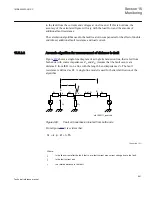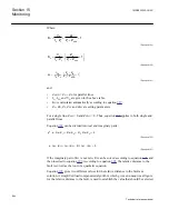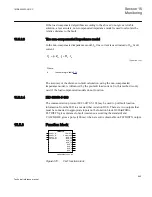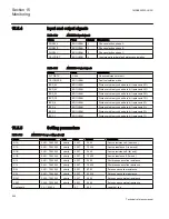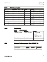
Where:
A
B
1
A
L
L
ADD
V
Z
K
1
I Z
Z
Z
=
+
+
×
+
EQUATION1601 V1 EN
(Equation 189)
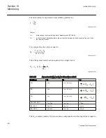
A
B
2
A
L
L
ADD
V
Z
K
1
I Z
Z
Z
=
×
+
×
+
æ
ö
ç
÷
è
ø
EQUATION1602 V1 EN
(Equation 190)
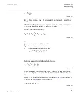
K
3
I
FA
I
A
Z
L
×
----------------
Z
A
Z
B
+
Z
1
Z
A DD
+
---------------------------
1
+
è
ø
æ
ö
×
=
EQUATION106 V1 EN
(Equation 191)
and:
•
Z
ADD
= Z
A
+ Z
B
for parallel lines.
•
I
A
, I
FA
and V
A
are given in the above table.
•
K
N
is calculated automatically according to equation
•
Z
A
, Z
B
, Z
L
, Z
0L
and Z
0M
are setting parameters.
For a single line, Z
0M
= 0 and Z
ADD
applies to both single and
parallel lines.
Equation
can be divided into real and imaginary parts:
p
2
p Re K
1
(
)
Re K
2
(
)
R
F
Re K
3
(
)
0
=
×
–
+
×
–
EQUATION107 V1 EN
(Equation 192)
p Im
K
1
( )
Im K
2
(
)
R
F
Im
K
3
(
)
0
=
×
×
–
×
+
×
×
–
EQUATION108 V1 EN
(Equation 193)
If the imaginary part of K
3
is not zero, R
F
can be solved according to equation
, and
then inserted to equation
, the relative distance to the
fault is solved as the root of a quadratic equation.
Equation
gives two different values for the relative distance to the fault as a
solution. A simplified load compensated algorithm, which gives an unequivocal figure
for the relative distance to the fault, is used to establish the value that should be selected.
Section 15
1MRK505222-UUS C
Monitoring
944
Technical reference manual
Summary of Contents for Relion 670 series
Page 1: ...Relion 670 series Line differential protection RED670 ANSI Technical reference manual...
Page 2: ......
Page 40: ...34...
Page 50: ...44...
Page 60: ...54...
Page 126: ...120...
Page 384: ...378...
Page 496: ...490...
Page 556: ...550...
Page 602: ...596...
Page 620: ...614...
Page 794: ...788...
Page 864: ...858...
Page 988: ...982...
Page 998: ...992...
Page 1084: ...1078...
Page 1164: ...1158...
Page 1168: ...1162...
Page 1220: ...1214...
Page 1230: ...1224...
Page 1231: ...1225...

