New
disturbance
From
disturbance
length control
per LED
set to
sequence 6
en01000237_ansi.vsd
AND
OR
AND
OR
OR
0
0-100s
tRestart
AND
OR
ANSI01000237 V1 EN
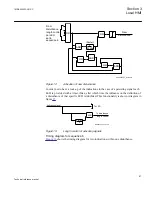
Figure 14:
Activation of new disturbance
In order not to have a lock-up of the indications in the case of a persisting signal each
LED is provided with a timer, tMax, after which time the influence on the definition of
a disturbance of that specific LED is inhibited. This functionality is shown i diagram in
figure
.
Activating signal
AND
To disturbance
length control
To LED
en05000507_ansi.vsd
0-tMax
0
ANSI05000507 V1 EN
Figure 15:
Length control of activating signals
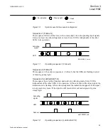
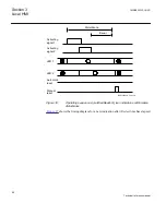
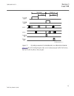
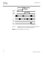
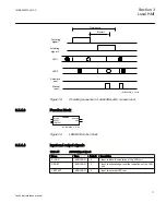
Timing diagram for sequence 6
shows the timing diagram for two indications within one disturbance.
1MRK505222-UUS C
Section 3
Local HMI
67
Technical reference manual
Summary of Contents for Relion 670 series
Page 1: ...Relion 670 series Line differential protection RED670 ANSI Technical reference manual...
Page 2: ......
Page 40: ...34...
Page 50: ...44...
Page 60: ...54...
Page 126: ...120...
Page 384: ...378...
Page 496: ...490...
Page 556: ...550...
Page 602: ...596...
Page 620: ...614...
Page 794: ...788...
Page 864: ...858...
Page 988: ...982...
Page 998: ...992...
Page 1084: ...1078...
Page 1164: ...1158...
Page 1168: ...1162...
Page 1220: ...1214...
Page 1230: ...1224...
Page 1231: ...1225...


