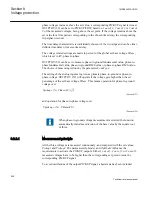
a>b
a
b
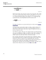
Vpickup>
V
t
tReset1
t
t1
AND
TRST1
PU_ST1
OFF
Delay
ON
Delay
ANSI10000100-2-en.vsd
ANSI10000100 V2 EN
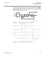
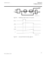
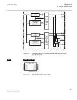
Figure 260:
Detailed logic diagram for step 1, DT operation
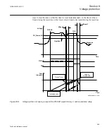
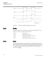
Pickup1
PICKUP
TRIP
tReset1
t1
ANSI10000037-2-en.vsd
ANSI10000037 V2 EN
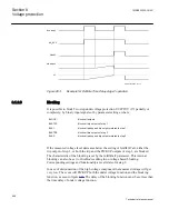
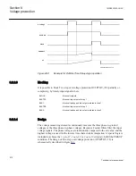
Figure 261:
Example for Definite Time Delay stage rest
1MRK505222-UUS C
Section 8
Voltage protection
511
Technical reference manual
Summary of Contents for Relion 670 series
Page 1: ...Relion 670 series Line differential protection RED670 ANSI Technical reference manual...
Page 2: ......
Page 40: ...34...
Page 50: ...44...
Page 60: ...54...
Page 126: ...120...
Page 384: ...378...
Page 496: ...490...
Page 556: ...550...
Page 602: ...596...
Page 620: ...614...
Page 794: ...788...
Page 864: ...858...
Page 988: ...982...
Page 998: ...992...
Page 1084: ...1078...
Page 1164: ...1158...
Page 1168: ...1162...
Page 1220: ...1214...
Page 1230: ...1224...
Page 1231: ...1225...

