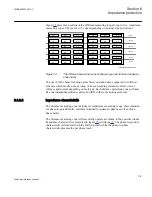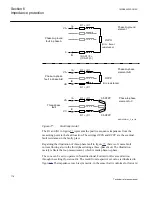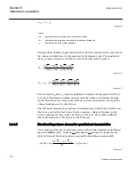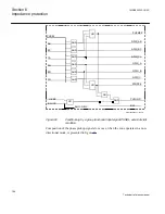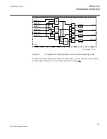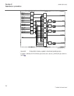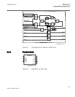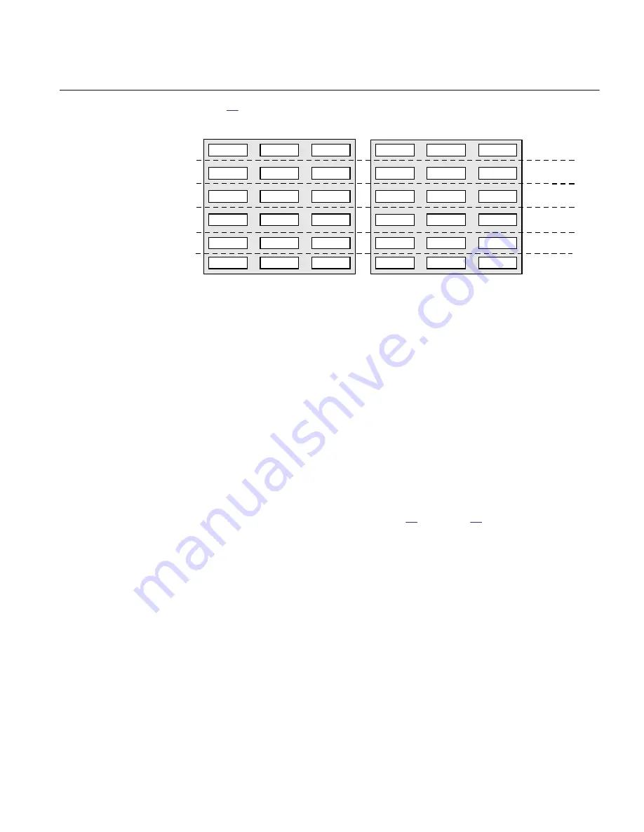
presents an outline of the different measuring loops for up to five, impedance-
measuring zones. There are 3 to 5 zones depending on product type and variant.
A-G
B-G
C-G
A-G
B-G
C-G
A-G
B-G
C-G
A-G
B-G
C-G
A- B
B-C
C-A
A- B
B-C
C-A
A- B
B-C
-A
A- B
B-C
C-A
A-G
B-G
C-G
A- B
B-C
C-A
Zone 1
Zone 2
Zone 3
Zone 4
Zone 5
C
Zone 6
A-G
B-G
C-G
A- B
B-C
C-A
ANSI05000458-2-en.vsd
ANSI05000458 V2 EN
Figure 74:
The different measuring loops at phase-to-ground fault and phase-to-
phase fault.
The use of full scheme technique gives faster operation time compared to switched
schemes which mostly uses a pickup of an overreaching element to select correct
voltages and current depending on fault type. Each distance protection zone performs
like one independent distance protection IED with six measuring elements.
6.1.3.2
Impedance characteristic
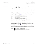
The distance measuring zone includes six impedance measuring loops; three intended
for phase-to-ground faults, and three intended for phase-to-phase as well as, three-
phase faults.
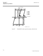
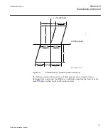
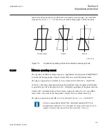
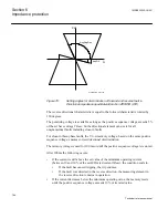
The distance measuring zone will essentially operate according to the non-directional
impedance characteristics presented in figure
characteristic is illustrated with the full loop reach while the phase-to-phase
characteristic presents the per phase reach.
1MRK505222-UUS C
Section 6
Impedance protection
175
Technical reference manual
Summary of Contents for Relion 670 series
Page 1: ...Relion 670 series Line differential protection RED670 ANSI Technical reference manual...
Page 2: ......
Page 40: ...34...
Page 50: ...44...
Page 60: ...54...
Page 126: ...120...
Page 384: ...378...
Page 496: ...490...
Page 556: ...550...
Page 602: ...596...
Page 620: ...614...
Page 794: ...788...
Page 864: ...858...
Page 988: ...982...
Page 998: ...992...
Page 1084: ...1078...
Page 1164: ...1158...
Page 1168: ...1162...
Page 1220: ...1214...
Page 1230: ...1224...
Page 1231: ...1225...

