


To be more certain that no new pulses are to be sent when the tap changer
is in operation, the tap changer operating signal can also be connected to the
LTC_BLOCK
input. In this case, the external blocking is achieved when an automatic
pulse is sent to the operating tap changer. The external
LTC_BLOCK
has by default
no effect when the active operation mode is set to "Manual" or "Parallel manual".
The status of the
TCO
input can be read from the
TCO
input data.
9.5.4.9
Blocking scheme
The operation of the voltage regulator can be blocked for several reasons. The
purpose of blocking is to prevent the tap changer from operating under conditions
that can damage the tap changer or exceed other power system-related limits.
The BLK_STATUS monitored data does not imply actual blocking but reveals if the
coming command pulse is issued or not. The blocking itself happens when the
corresponding bit in the signal BLK_STATUS is active and the command pulse is
started due to a timer elapse or a local command. This is to avoid unnecessary
event sending.
The BLK_STATUS monitored data is also packed. It contains information about the
blocking status as bit-coded output. The block status output does not indicate
the actual blocking but indicates if the coming command is successful. The actual
blocking is indicated by studying the corresponding monitored data (BLK_I_LOD,
BLK_U_UN, RNBK_U_OV, BLK_LTCBLOCK, BLK_I_CIR, BLK_RAISE and BLK_LOWER)
illustrates the meaning of different monitored data values. For
example, the block status value 9 indicates that there are conditional circulating
current and load current blockings (8 + 1 = 9) indicated. By default, the status is “0”.
Table 1015: Bit-coded block status and the meaning of different bits
Bit
Active value
Blocking reason
6 (msb)
64
Lowest position reached
5
32
Highest position reached
4
16
External LTC_BLOCK
3
8
High circuit current
2
4
Overvoltage - Runback raise voltage
1
2
Undervoltage - Block lower voltage
0 (lsb)
1
Overcurrent - Load current
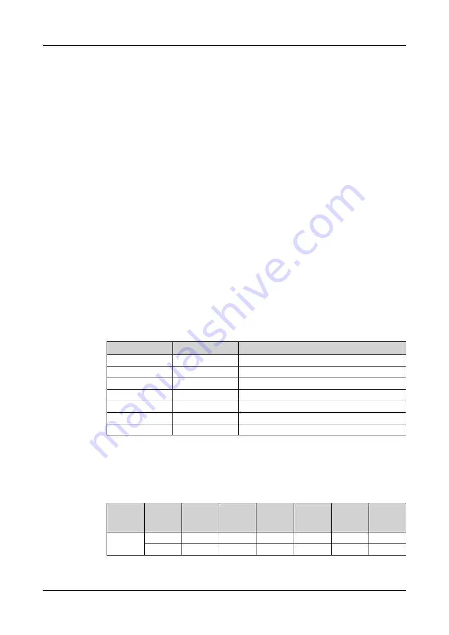
The cross (X) in the table defines when the operation is blocked (if the
corresponding bit is active in BLK_STATUS). For example, an overvoltage (runback
raising voltage) results in blocking only when the acting operation mode is "Manual"
and the manual raising command is given.
Table 1016: Default blocking schema in OLATCC
Acting
operation
mode
Comman
d
Load
current
Block
lowering
voltage
Runback
raising
voltage
High
circulatin
g current
External
Block
Extreme
positions
Manual
Raise
X
X
X
Lower
X
X
Table continues on the next page
Control functions
1MRS757644 H
1062
620 series
Technical Manual


