ABB ReliaGear ND Installation, Operation And Maintenance Manual Download Page 6

6

R E LI AG E A R

®

 N D A NS I  N A R ROW  DE S IG N  ME TA L- CL A D  S WITCHG E A R

Receiving, handling and storage

Receiving inspection
Before shipment, the equipment is inspected and 
marked with its number and position. Switchgear 
frames are factory-assembled and shipped with the 
doors closed. The factory ships circuit breakers in 
separate cartons, or as an option, inside the 
switchgear frame with the breakers in disconnect 
position.

Upon receipt of the equipment, examine the 
shipment for damage or missing components. 
Check the contents against the packing list before 
discarding any packing material. Check the 
consignment for completeness and lack of any 
damage (e.g., moisture and its detrimental effects). 
In case of doubt, the packing must be opened and 
then properly resealed, putting in new drying agent 
bags, when intermediate storage is necessary.

If any quantities are short, or defects or transport 
damage are noted, these must be documented on 
the respective shipping document. Notify ABB and 
the carrier at once of any discrepancies. If there is 
damage from improper handling, file a claim for 
damages at once with the carrier and notify ABB. 
Always photograph damage. Unless otherwise 
noted in the project contract documents, ABB 
standard shipments are “FOB Factory.” ABB is  
not responsible for damage after delivery of 
the equipment to the carrier.

3.2 Handling the equipment
Transport panels upright. Take the high center  
of gravity into account. Carry out loading 
operations only when it has been ensured that all 
precautionary measures to protect personnel and 
materials have been taken into consideration.

Notice: All doors and panels must be in place and 
securely fastened before moving the equipment. 

Storing the equipment
Leave the equipment on the shipping base. Store  
all equipment indoors in a well-ventilated area.

The storage building should have a well-drained 
paved floor. The temperature should be above 60 °F.  
The air should be dry (60% maximum humidity).

The shipping sections are ship wrapped in plastic  
for protection during shipment only. Remove the 
plastic wrap after placing into storage. Cover with 
heavy wrapping paper or other moisture barrier.  
Use materials that will not trap moisture inside the 
unit. Do not cover louvered openings.

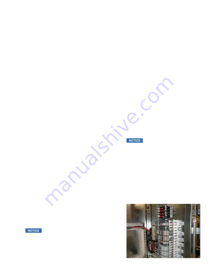
For long-term storage, i.e., durations exceeding  
two weeks, or in high-humidity areas, use heaters  
to keep the interior dry. Bring power for the heaters 
to the load terminals of the device that controls the 
heater circuits (figure 1). 


   Notice: Remove all the packing 

materials from the switchgear  
before energizing the heaters. 
 
Open the breaker or cutout device 
that controls the heaters when using 
a separate power source. 

For circuit breakers shipped in crates, store circuit 
breakers upright in their original shipping carton 
oriented as indicated on the shipping crates. For 
circuit breakers shipped in the switchgear, do not 
remove for storage. See document 1VAL057601-MB 
for details on breaker storage.


01 Heater load  
terminals in low  
voltage compartment


01 

Summary of Contents for ReliaGear ND

Page 1: ... INSTALLATION OPER ATIONS AND MAINTENANCE MANUAL ReliaGear ND ANSI narrow design metal clad switchgear ...

Page 2: ......

Page 3: ...es and warnings 05 Introduction 06 Receiving handling and storage 07 Site preparation 08 18 Indoor installation 19 20 Testing and final inspection 21 Placing switchgear into service safety precautions 22 Standard construction 23 27 Maintenance ...

Page 4: ...n which if not avoided could result in minor or moderate injury Notice is used to address practices not related to physical injury Although warning hazards are related to personal injury it is necessary to understand that under certain operational conditions operation of damaged equipment may result in degraded process performance leading to personal injury or death therefore comply fully with all...

Page 5: ... useful life Scope of instructions The instructions are general in nature They cover requirements for installation setup checkout and maintenance as applied to ReliaGear ND medium voltage non arc resistant switchgear These instructions do not attempt to cover all variations and combinations of equipment and installations Information on particular installations appears in the following Bills of mat...

Page 6: ...high center of gravity into account Carry out loading operations only when it has been ensured that all precautionary measures to protect personnel and materials have been taken into consideration Notice All doors and panels must be in place and securely fastened before moving the equipment Storing the equipment Leave the equipment on the shipping base Store all equipment indoors in a well ventila...

Page 7: ... the front should allow for installation and removal of the draw out equipment A minimum of 7 3 is recommended Provide rear access of 4 minimum for making connections before start up and for periodic inspections and maintenance Breaker doors can swing 115o with adjacent doors closed Foundation The ABB factory supplies general arrangement and floor plan drawings for each installation Refer to these...

Page 8: ...Forklift Place forks through locations provided in the shipping bases figure 2 figure 3 Make sure that forks have penetrated the entire depth of the switchgear to engage all three shipping channels front center and rear figure 4 Lift the switchgear frames slowly and tilt forks slightly rearward to balance Move carefully into the final position taking into account the center of gravity figure 5 Tow...

Page 9: ...on Select four pieces of wood thick enough to permit removal of the jack after lowering Place one under each corner Slowly lower one side until it rests on the pieces of wood Repeat this process on the other side Use a pry bar to lift each corner enough to remove the four pieces of wood Attaching to the floor Following the removal of the shipping bases the switchgear units should be secured to the...

Page 10: ...h to ground Installation of bus bar connections between shipping splits The factory assembles the main bus bar in each section The splices at the shipping splits are unbolted for shipment Refer to the general arrangement drawings The contact surfaces of the bus at bolted joints are plated Clean contact surfaces with a clean cloth and an OSHA approved solvent Caution Do not use alcohol or freon Lim...

Page 11: ...re made of 1 8 aluminum these plates must be used in the final assembly Holes for entrance of power cables or conduits must be cut in the gland plate s and a sealing type bushing used ABB recommends using O Z Gedney sealing bushings for all installations Warning Sealing bushings are required for all power cable entries Connection to control source The control source wiring should be properly sized...

Page 12: ...the circuit breaker The circuit breaker may be locked out by padlocking both the racking port and door handle It is recommended to use flat lockout hasps on both provisions figure 10 Insertion 1 Open the breaker module door completely figure 11 Door stops if available can be used to keep the door in position when operating the equipment 2 Use the lift truck for breakers to be installed in the uppe...

Page 13: ... locking tab and interlock release handle 14 Breaker lift truck pan side view 15 Breaker lift truck winch 16 Lift truck foot pedal 17 Lift truck holding Vmax A 15 13 16 Breaker locking tab Interlocking release handle 14 Locking slots 17 ...

Page 14: ... truck by pulling both module interlock release handles toward the center of the breaker simultaneously 6 Push the circuit breaker straight into the module Keep the breaker as level as possible Do not raise or lift the circuit breaker 7 Align the breaker locking tabs with the module interlock slots figure 20 8 Engage the breaker locking tabs by returning the handles to their outward position 9 Ver...

Page 15: ...sition 2 Close the circuit breaker door If a door stop was used the door may be released by lifting the bar the hardware will then move along the track 3 Move the racking port padlock provision into the open position 4 Engage the racking screw with the racking tool and rotate clockwise CW figure 23 5 Continue to rack the circuit breaker by rotating the racking tool clockwise A slight increase in r...

Page 16: ...ker straight onto the lift truck platform Keep the drawout element level as possible 6 Align the breaker interlock tabs with the lift truck slots Engage the breaker interlock tabs by returning the handles to their outward position 7 Verify that the handles are fully outward and the breaker interlock tabs are in the lift truck slots 8 Raise the lift truck slightly to disengage the platform hooks Re...

Page 17: ...to release the interlock lever For PT or CPT elements in the upper position the push pull extension may be used to ease operation figure 27 The extension can be added by inserting the extension into the push pull tool and securing it with a clevis pin It can also be disassembled for storage 26 5 Push the rod into the compartment to insert the CPT or PT element The rod is held captive while between...

Page 18: ... door and insert the push pull rod into the push pull port Turn the handle to release the interlock lever 4 Pull the rod to withdraw the CPT or PT element The rod is held captive while between disconnect and connect positions 5 When the device is fully disconnected the rod can be returned to its original insertion orientation and removed from the push pull port To withdraw the CPT or PT drawout el...

Page 19: ...hen making DC tests raise the voltage to the test value in discrete steps and hold for one 1 minute 5 With the main circuit de energized and grounded check the continuity of all circuits after installing the circuit breakers Energize the control source and operate the equipment Indicating instruments verify the continuity of current transformer circuits and energizing of the main circuit Control c...

Page 20: ...t each is connected to control power 8 Test all electrically and manually operated breakers for closing and tripping while they are in the TEST position 9 De energize the control circuit If AC control power is from transformers in the switchgear remove the temporary separate source of control power Reinstall all fuses in the transformer circuit 10 Set all relays regulators and other devices for pr...

Page 21: ...ce of the incoming power source before making connections Notice Never open circuit the secondary circuits of energized current transformers The contact surfaces of the bus at bolted joints are plated Clean contact surfaces with a clean cloth and an OSHA approved solvent Bolt the bus together Conductivity of a bolted joint depends on the pressure or torque applied All bolted joints must be torqued...

Page 22: ...te coating This process achieves a smooth uniform paint finish that conforms to applicable UL requirements Galvanized steel frame construction Unpainted parts are made of galvanized steel Galvanized steel greatly exceeds the paint qualifications of ANSI C37 20 2 Section 5 2 8 Bus support insulation The bus supports figure 30 are indoor epoxy type The supports ensure safe operational clearances of ...

Page 23: ...bolted connections 6 Look for evidence of moisture in the switchgear Evidence of moisture can be but not limited to water droplets condensation oxidized metal etc 7 Inspect all cables for tight connections and ample support 8 Inspect control wiring for signs of wear and damage especially at door hinge locations Replace wire wherever doubtful 9 Examine resistors and other devices prone to overheati...

Page 24: ...1 Disassemble inspect clean lubricate adjust and calibrate circuit breaker mechanisms as recommended in the instructions furnished with the circuit breaker 2 Torque all primary conductor connection bolts to recommended values All bolted joints must be torqued per the values in appendix A target torque values 3 Tighten all secondary control wire connections Check for loose lug crimps and broken wir...

Page 25: ... with No Ox ID Special A Compound a product of Sanchem Chemical Co ABB part no 713222A00 or equivalent 7 Use proper torque in tightening bolted connections All bolted joints must be torqued per the values in appendix A target torque values Care of finish The paint and galvanized finish is strong and durable Always keep the switchgear clean Wiping with a clean dry cloth will usually suffice To remo...

Page 26: ... of product ABB products are manufactured to meet or exceed the standards of compliance for quality and environmental management systems in accordance with ISO 9001 and ISO 14001 All of these items can be supplied with a certificate of quality Methods of disposal Disposal can be carried out in a manner of ways depending upon the material of the product Below is the recommended method of disposal f...

Page 27: ...ive or covering all contingencies No warranties expressed or implied including warranties of fitness for a particular purpose or merchantability or warranties of fitness for a particular purpose or merchantability or warranties arising from course of dealing or usage of trade are made regarding the information recommendations descriptions and safety notations contained herein In no event will ABB ...

Page 28: ...rs the agreed particulars shall prevail ABB Inc does not accept any responsibility whatsoever for potential errors or possible lack of information in this document We reserve all rights in this document and in the subject matter and illustrations contained therein Any reproduction disclosure to third parties or utilization of its contents in whole or in parts is forbidden without prior written con...

Reviews: