9.
Check the inverse time delay by injecting a voltage corresponding to 0.8 ×
U1<.
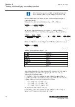
For example, if the inverse time curve A is selected, the trip
signals TR1 and TRIP operate after a time corresponding to
the equation:
t s
k
U
U
( )
=
−
<
1
1
1
IECEQUATION2428 V1 EN-US
(Equation 87)
where:
t(s)
Operate time in seconds
k1
Settable time multiplier of the function for step 1
U
Measured voltage
U1<
Set start voltage for step 1
For example, if the measured voltage jumps from the rated value to 0.8 times
the set start voltage level and time multiplier k1 is set to 0.05 s (default
value), then the TR1 and TRIP signals operate at a time equal to 0.250 s ±
tolerance.
10. The test above can be repeated to check the inverse time characteristic at
different voltage levels.
11. Repeat the above described steps for Step 2 of the function.
Extended testing
M13796-35 v8
The tests above can be repeated for
2 out of 3
and for
3 out of 3
operation mode.
9.5.1.2
Completing the test
M13796-25 v5
Continue to test another function or end the test by changing the
TESTMODE
setting to
Off
. Restore connections and settings to their original values, if they were
changed for testing purposes.
9.5.2
Two step overvoltage protection OV2PTOV
M13806-2 v6
Prepare the IED for verification of settings outlined in Section
9.5.2.1
Verifying the settings
M13806-9 v2
Verification of single-phase voltage and time delay to operate for
Step 1
M13806-50 v9
Section 9
1MRK 506 383-UEN A
Testing functionality by secondary injection
124
Line distance protection REL650 2.2 IEC
Commissioning manual
Summary of Contents for REL650 series
Page 1: ...RELION 650 SERIES Line distance protection REL650 Version 2 2 Commissioning manual...
Page 2: ......
Page 24: ...18...
Page 28: ...22...
Page 38: ...32...
Page 54: ...48...
Page 58: ...52...
Page 178: ...172...
Page 182: ...176...
Page 188: ...182...
Page 196: ...190...
Page 206: ...200...
Page 207: ...201...


