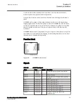
These signals shall be used for communication based earth-fault teleprotection
communication schemes (permissive or blocking).
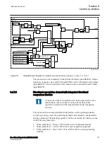
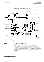
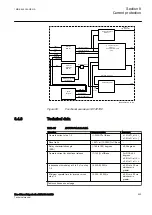
Simplified logic diagram for directional supervision element with integrated
directional comparison step is shown in Figure
X
a
a>b
b
IN>Dir
polMethod=Voltage
polMethod=Dual
OR
FORWARD_Int
REVERSE_Int
BLOCK
STAGE1_DIR_Int
0.6
X
0.4
AND
STAGE3_DIR_Int
STAGE4_DIR_Int
STAGE2_DIR_Int
OR
STRV
UPolMin
IPolMin
AngleRCA
T
F
0.0
X
T
F
RNPol
XNPol
0.0
Direc
tional
Characteristic
FWD
RVS
AND
AND
AND
STFW
FORWARD_Int
REVERSE_Int
AND
IEC07000067-6-en.vsdx
|
|
UPol
UIPol
IPol
I3PDIR
UTotPol
IopDir
Complex
Number
a
a>b
b
T
F
0.0
polMethod=Current
OR
IEC07000067 V6 EN-US
Figure 87:
Simplified logic diagram for directional supervision element with integrated directional
comparison step
8.4.7.9
Second harmonic blocking element
M13941-200 v8
A harmonic restrain can be chosen for each step by a parameter setting
HarmBlockx
. If the ratio of the 2nd harmonic component in relation to the
fundamental frequency component in the residual current exceeds the preset level
(defined by parameter
2ndHarmStab
), output signal 2NDHARMD is set to logical
value one and the harmonic restraining feature to the function block will be
applicable.
Blocking from the 2nd harmonic element activates if all of three criteria are
satisfied:
1MRK 505 394-UEN A
Section 8
Current protection
Line differential protection RED650 2.2 IEC
199
Technical manual
Summary of Contents for RED650
Page 1: ...RELION 650 SERIES Line differential protection RED650 Version 2 2 Technical manual...
Page 2: ......
Page 36: ...30...
Page 46: ...40...
Page 232: ...226...
Page 272: ...266...
Page 288: ...282...
Page 306: ...300...
Page 406: ...400...
Page 436: ...430...
Page 502: ...496...
Page 614: ...608...
Page 628: ...622...
Page 644: ...638...
Page 760: ...754...
Page 778: ...772...
Page 814: ...808...
Page 870: ...864...
Page 874: ...868...
Page 924: ...918...
Page 925: ...919...

