


16.1.5
General current transformer requirements
The current transformer ratio is mainly selected based on power system data for example,
maximum load. However, it should be verified that the current to the protection is higher
than the minimum operating value for all faults that are to be detected with the selected CT
ratio. The minimum operating current is different for different functions and normally
settable so each function should be checked.
The current error of the current transformer can limit the possibility to use a very sensitive
setting of a sensitive residual overcurrent protection. If a very sensitive setting of this
function will be used it is recommended that the current transformer should have an
accuracy class which have an current error at rated primary current that is less than ±1%
(for example, 5P). If current transformers with less accuracy are used it is advisable to
check the actual unwanted residual current during the commissioning.
16.1.6
Rated equivalent secondary e.m.f. requirements
With regard to saturation of the current transformer all current transformers of high
remanence and low remanence type that fulfill the requirements on the rated equivalent
limiting secondary e.m.f. E
al
below can be used. The characteristic of the non remanence
type CT (TPZ) is not well defined as far as the phase angle error is concerned. If no explicit
recommendation is given for a specific function we therefore recommend contacting ABB
to confirm that the non remanence type can be used.
The CT requirements for the different functions below are specified as a rated equivalent
limiting secondary e.m.f. E
al
according to the IEC 61869-2 standard. Requirements for
CTs specified according to other classes and standards are given at the end of this section.
16.1.6.1
Breaker failure protection
The CTs must have a rated equivalent secondary e.m.f. E
al
that is larger than or equal to
the required secondary e.m.f. E
alreq
below:
Section 16
1MRK 511 286-UUS A
Requirements
348
Application manual
Summary of Contents for REC650 ANSI
Page 1: ...Relion 650 series Bay control REC650 ANSI Application manual...
Page 2: ......
Page 26: ...20...
Page 66: ...Section 3 1MRK 511 286 UUS A REC650 setting examples 60 Application manual...
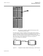
Page 71: ...IED IED ANSI05000460 V2 EN 1MRK 511 286 UUS A Section 4 Analog inputs 65 Application manual...
Page 82: ...76...
Page 92: ...86...
Page 170: ...164...
Page 176: ...170...
Page 274: ...268...
Page 288: ...282...
Page 350: ...344...
Page 369: ...363...


