


There are no settings for AND gates, OR gates, inverters or XOR gates as well as, for
ANDQT gates, ORQT gates or XORQT gates.
For normal On/Off delay and pulse timers the time delays and pulse lengths are set from
the local HMI or via the PST tool.
Both timers in the same logic block (the one delayed on pick-up and the one delayed on
drop-out) always have a common setting value.
For controllable gates, settable timers and SR flip-flops with memory, the setting
parameters are accessible via the local HMI or via the PST tool.
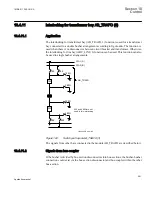
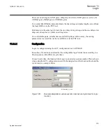
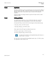
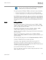
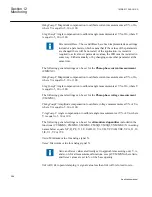
11.3.3.1
Configuration
Logic is configured using the ACT configuration tool in PCM600.
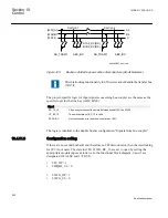
Execution of functions as defined by the configurable logic blocks runs according to a
fixed sequence with different cycle times.
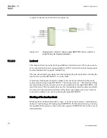
For each cycle time, the function block is given an serial execution number. This is shown
when using the ACT configuration tool with the designation of the function block and the
cycle time, see example below.
IEC09000695_2_en.vsd
IEC09000695 V2 EN
Figure 128:
Example designation, serial execution number and cycle time for logic
function
1MRK 511 286-UUS A
Section 11
Logic
275
Application manual
Summary of Contents for REC650 ANSI
Page 1: ...Relion 650 series Bay control REC650 ANSI Application manual...
Page 2: ......
Page 26: ...20...
Page 66: ...Section 3 1MRK 511 286 UUS A REC650 setting examples 60 Application manual...
Page 71: ...IED IED ANSI05000460 V2 EN 1MRK 511 286 UUS A Section 4 Analog inputs 65 Application manual...
Page 82: ...76...
Page 92: ...86...
Page 170: ...164...
Page 176: ...170...
Page 274: ...268...
Page 288: ...282...
Page 350: ...344...
Page 369: ...363...


