


22
PQSTOR I
I N S TR U C TI O N M A N UA L
The Wi-Fi user interface communicates with
the module that has the lowest address in the
WARNING:
Failing to set switch 7 properly will
lead to malfunction and damage the equipment.
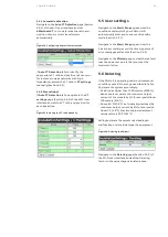
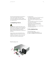
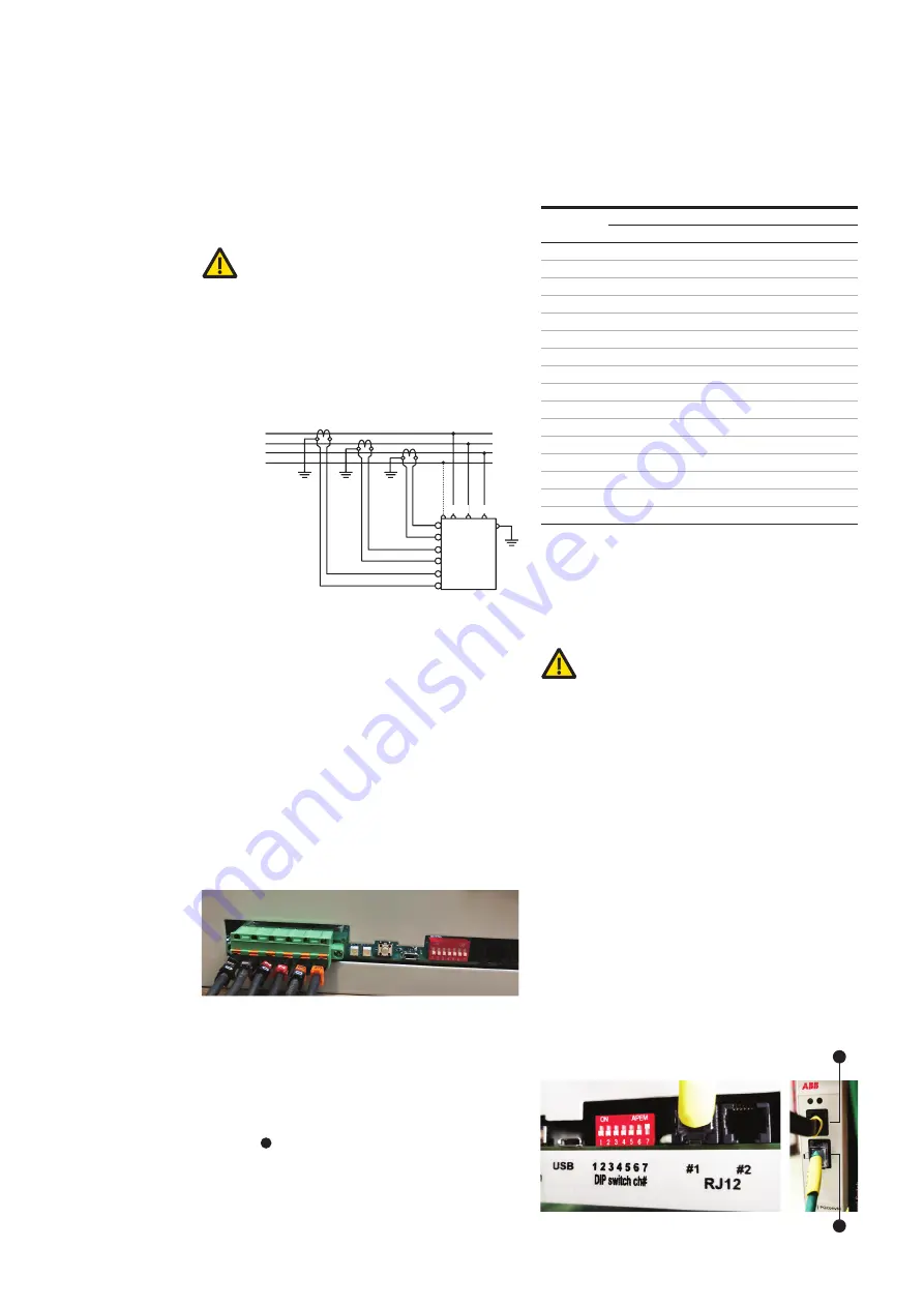
4.7 Modbus
An external controller (e.g. an Energy Managem-
ent System) can be used to operate the PQstorI
remotely, provided that it can communicate with
the PQstorI over Modbus. To establish this
connection, plug an Ethernet cable with an RJ45
connector (not provided, use Cat5e or more
advanced) to the PQconnecT as illustrated in X of
Figure 19. For a list of key Modbus commands
used to operate the PQstorI, refer to Section 3.2.
4.5.5 Current transformers (optional)
The purpose of the connection with current
transformers is to allow the use of power quality
functionalities that will be available in the future.
Due to that, the connection with CTs is not
mandatory yet.
WARNING:
Only a qualified electrician should
perform the operations described in this section.
Connect a current transformer (CT) to each phase
line of the network as described in Figure 17.
The operating conditions of the PQstorI require
class 1.0 X/ 5A CT that can withstand 15 VA over
20 meters of 2.5 mm2 (14AWG) cables. Insert each
CT wire into the appropriate pole of the spring-
contact female plug on the front panel of the
module (Figure 18).
—
NOTE: The CTs terminals in the inverters are
suitable for 0,5mm² (20AWG) to 4mm² (12AWG),
75
o
C, copper conductors only.
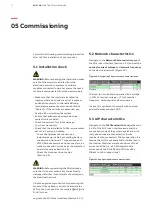
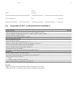
4.6 Addressing the module
The inverter has a DIP switch that allows to
define a unique binary address to the unit. The
DIP switch is located on the front panel of the
inverter ( in Figure 2).
The first four switches on the left of the DIP
switch module can be moved to ↑ or ↓ positions
to assign this binary address (see Table 15).
—
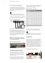
Figure 18: CT connections to the module
—
Figure 17: Basic CT connection diagram
L1
K L
k I
k I
k I
K L
K L
L2
L3
N
I3
k3
l2
k2
I1
k1
Supply
side
Load
side
Ac power
supply
L1 L2 L3
N
C
T inpu
ts
Module
K=P1, L=P2, k=S1, I=S2
Switch 7 determines the CAN termination of the
module. Set it to ↑ for the last module in the
system and to ↓ for all others.
—
Table 15: Possible DIP switch settings
* Set the switch 7 to ↑ for the last module in your system and to ↓ for
all others.
Address
DIP switch position
1
2
3
4
7
1
↓
↓
↓
↓
↓
2
↑
↓
↓
↓
↓*
3
↓
↑
↓
↓
↓*
4
↑
↑
↓
↓
↓*
5
↓
↓
↑
↓
↓*
6
↑
↓
↑
↓
↓*
7
↓
↑
↑
↓
↓*
8
↑
↑
↑
↓
↓*
9
↓
↓
↓
↑
↓*
10
↑
↓
↓
↑
↓*
11
↓
↑
↓
↑
↓*
12
↑
↑
↓
↑
↓*
13
↓
↓
↑
↑
↓*
14
↑
↓
↑
↑
↓*
15
↓
↑
↑
↑
↓*
16
↑
↑
↑
↑
↑
—
Figure 19: PQconnecT and Modbus connection
Y
X
7


