


04-3788_ABB_OPM_PVA11 6-10kVA-RT_EN_140423
Page 14/37 ABB
Modifications reserved
Model
6 kVA
10 kVA
Protective Earth (PE) conductor
(Minimum cross section)
6mm2 (8 AWG)
10mm2 (6 AWG)
Input L, N, G (
Minimum cross section)
6mm2 (8 AWG)
10mm2 (6 AWG)
Input fuse
60A
80A
Output L,N, G
(Minimum cross section)
6mm2 (8 AWG)
10mm2(6AWG)
External Battery Cabinet
Positive Pole(+), Negative Pole(-), Neutral Pole
(Minimum cross section)
4mm2
(10
AWG)
2.5mm2*2
(12 AWG*2)
External Battery Cabinet Fuse in Positive
Pole(+), Negative Pole (-), Neutral Pole
60A
80A
Figure 11: Recommended Cables and Fuses
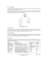
It is suggested to install an external isolating device against back-feed currents between mains input and UPS
as indicated in Figure 12.
AC Contactor:
208-240V, 50A (PowerValue 11 RT 6 kVA)
208-240V, 70A (PowerValue 11 RT 10 kVA)
Figure 12: External Backfeed Isolation
WARNING!
AFTER THE DEVICE IS INSTALLED, ADD A LABEL WITH THE
FOLLOWING WARNING ON THE EXTERNAL AC CONTACTOR: “
RISK OF
BACKFEED VOLTAGE. ISOLATE THE UPS BEFORE OPERATING ON
THIS CIRCUIT AND CHECK FOR HAZARDOUS VOLTAGE
”
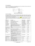
2.4.3
Connections
To access the terminal blocks, remove the 2 screws from the terminal block cover.
Figure 13: PowerValue 11 RT 6 kVA Terminal block
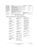
Figure 14: PowerValue 11 RT 10 kVA Terminal block