


Operation Manual / Power2 845-M / 4.1 Low-pressure stage
4 Disassembly and assembly / 4.13 Installing the wall insert
© Copyright 2018 ABB. All rights reserved.
HZTL4068_EN
Revision A
March 2018
4.13
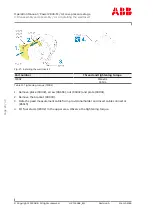
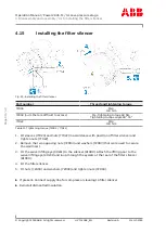
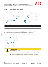
Installing the wall insert
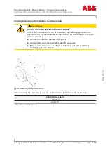
CAUTION
Clearance between compressor wheel and wall insert
Serious damage to machinery or property can result from rubbing or jam-
ming of the compressor wheel at the wall insert.
u
Check that the compressor wheel does not rub against the wall insert
during disassembly/assembly by rotating the rotor.
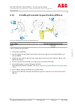
Fig. 26: Installing the wall insert 1
Part number
Thread and tightening torque
77016
M5x30
5 Nm
Table 12: Tightening torque (77016)
1. Coat thread of screws (77016) with Loctite® 243 and secure diffuser (79000) with
screws (77016). Observe the tightening torque.
2. Install new O-rings (77040 / 79020 / 79021).
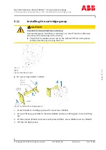
3. Secure lifting gear to swivel lifting eye (90231).
4. Fit one plate (90031) and secure with plate (90032), screw (90656) and nut (90432).
5. Lift the wall insert and remove the support angle (90480).
6. Carefully insert the wall insert.
7. Fix the wall insert in place with two opposing nuts (72004) and washers (72003).
Page
27
/
43