41-973.5R
11
Type PM Line of Relays For Pilot Wire Monitoring
And Transferred Tripping
13, and PM-23 relays, adjust the contacts as
described in the previous paragraph, except back off
the contact and stop screws one-half turn each to
give a total moving contact travel of approximately
0.025 inch.
In operation of the tripping unit, the moving contact
will normally rest against the contact stop screws,
and will pickup only for a transferred tripping opera-
tion.
For the pilot-wire ground alarm unit (5) of the PMA,
PMD, PM-5, and PMG-13 relays, follow the same
general procedure except back off both stationary
contact screws two turns each. This will give a con-
tact tap of 0.050 on each side of the moving contact
when it is in its normal central position.
9.1.3
Contact Gap
The contact gap between the floating moving contact
and the right-hand or left-hand stationary contacts of
contact stops must not be less than 25% of the over-
all stationary-to-stationary contact gap, i.e., with an
overall contact gap of .100 excluding dimension of
moving contact, the gap of the floating contact to
either stationary contact can be .025 to 0.75.
9.1.4
Electrical Calibration – all relays
In the following sections, the calibration instructions
are given for the polar unit which performs a certain
function, such as alarm (1) or (2), ground (5), or trip
(3), rather than giving calibration instructions for each
complete relay. In this way, considerable duplication
of instructions has been eliminated.
9.1.5
Alarm Unit (1)
Connect the relay as described under the “Accep-
tance Tests” section, for the particular relay involved.
Screw the two magnetic shunts all the way in, then
back them out five turns each. With the relay ener-
gized at rated voltage, set the monitoring current at
1.3 or 2.3 mA dc for 2 or 3 terminal relay respectively,
by adjusting the external resistor. If the relay does
not close its right-hand contact, turn in the left shunt
screw until the right-hand contact just closes. If the
right-hand contact is closed at 1.3 mA, turn in the
right shunt until a point is reached when the right-
hand contact is just closed at 1.3 mA.
Now drop the current to 0.65 mA and adjust the
opposite shunt until the left-hand contact just closes
at 0.65 mA dc. At 1.0 mA dc the moving contact
should float half way between the two sets of station-
ary contacts with a 0.025 inch gap on each side.
Recheck the high and low current calibration several
times, touching up the shunt adjustments as required
to obtain the desired calibration.
9.1.6
Polarization Check
For all source relays, which are listed below, make
the following additional calibration check:
After calibration as described in the previous sec-
tions, connect a 20,000 ohm resistor (or 10,000
ohms for 3-terminal applications) across the output
terminals, and energize the relay at its rated supply
voltage. With these connections, approximately one
(or two) milliamperes dc will flow through the monitor
relay coils and external resistor, thus representing
normal operating conditions.
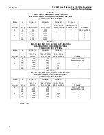
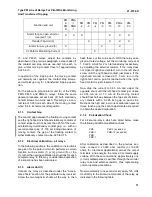
Now momentarily (one second or so) apply 125 volts
dc directly to the pilot-wire terminals of the relay, as
indicated in the following table.
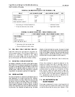
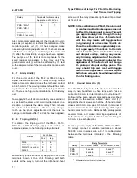
PMA
PMA-1
PMD
PMD-1
PM-13 (ac and dc)
PMG-13 (ac and dc)
Function and unit
PM
A
PM
D
PMA
-1
PMD
-1
PM
-2
PM
-3
PM
-4
PM
-5
PM-
13
PMG-
13
PM-
23
Alarm for p.w. open, short or
reversal (1) (2)
X
X
X
X
X
X
Transfer Trip Unit (3)
X
X
X
X
Alarm for p.w. ground (5)
X
X
X
dc Path for Monitoring Current
X

