


Page 2–14
2101510 Rev. AG
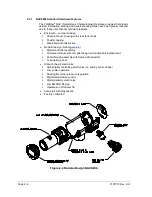
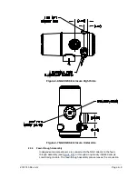
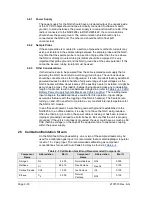
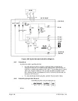
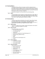
2.3.6
Digital Controller Assembly with VGA Display
This assembly (see
) contains the digital electronic board, mounting
assembly and a VGA display.
The digital controller board provides control parameters to the analytical processor
board and stores and processes the data sent from the analytical processor
board. The digital controller also processes communication with other devices.
The digital electronic board features:
•
16 MB Pseudo Static Ram (Application), Lithium Battery backed
•
32 MB NAND Flash Memory (Boot/Application/Storage)
•
4 MB Static CMOS Memory (Storage)
•
1 secure digital card socket, with up to 4 GB removable storage optional)
Figure 2-13 Digital Controller Assembly with Display
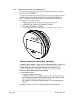
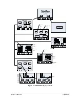
The display board provides a ¼ panel, VGA monochromatic display to monitor the
process and results. It also provides six magnetic switches to allow a user to
navigate through various screens of data and control the processes (stop
operation, start operation and calibrate). Available screens and user-defined
screens may be navigated using the display magnet.
The VGA display features:
•
¼ panel VGA display circuit board.
•
2 LED Status Indicators, user-programmable. The default left LED- flashing
light indicates a fault alarm, and a solid light indicates a warning alarm. Right
LED- solid light indicates unit is not in auto run mode.
•
User interface, with hall-effect magnet navigation, for monitoring NGC8200
operation.
shows the flow of information accessible through the display.
A
B
B


