2101510 Rev. AG
Page 6–27
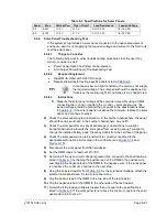
Table 6–3 Specifications for Solar Panels
Panel
Max
Volts at P
Max
Open Circuit
Load Resistance
Loaded Voltage
50
54 W
17.4 V
21.7 V
5 Ω 100 W
16–18 VDC
85
87 W
17.4 V
21.7 V
5 Ω 100 W
16–18 VDC
6.5.6
Solar Panel Troubleshooting Test
If the system setup includes a solar panel connected to the optional equipment
enclosure, and it is not supplying the required voltage and current to the NGC unit,
test the solar panel.
6.5.6.1
Things to Consider
The following list points to other troubleshooting procedures that the user may
want to consider as well:
•
Power Consumption Test (Remote Equipment)
•
AC Charger/Power Supply Troubleshooting Test
6.5.6.2
Required Equipment
•
Digital Multi-meter with 0-20 VDC range.
•
Required resistors for testing specific panels listed in
In continuous low sun light conditions, the unit may not supply
the required voltage. The solar panel should be positioned so
it receives the most sunlight. Do not place it in a shaded area.
6.5.6.3
Instructions
1)
Measure the solar panel voltage at the controller assembly using a DMM
connecting the (+) and (-) leads to the (+) and (-) solar panel wires. The
loaded voltage should be greater than or equal to the specifications listed
in
. If the solar panel is not above the minimum, replace the solar
panel, and continue to step 2.
2)
Check the solar panel angle and direction. In the northern hemisphere, the panel
should face due south and in the southern hemisphere, due north.
3)
Check the solar panel for any physical damage or obstructions to sunlight.
Sunlight obstruction prevents the solar panel from receiving enough sunlight to
charge the installed battery pack. Clear any debris from the cell face of the panel.
4)
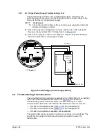
Check the solar panel wiring to be certain it is correctly connected to the
associated termination pins located in the enclosure (see
5)
Disconnect the solar panel from the field device.
6)
Set the DMM range to read over 20 VDC.
7)
Determine if the open circuit voltage is greater than or equal to the specifications
listed in
by clipping the positive lead of the DMM to the positive wire
and clipping the negative lead of the DMM to the negative wire. If the solar panel
is not above the minimum, continue to the next step.
8)
Using the selected resistor from
for the solar panel wattage, attach the
selected resistor between the two solar panel wires.
9)
Clip the positive lead of the DMM to the one side of the test resistor.
10)
Clip the negative lead of the DMM to the other side of the test resistor.
11)
Determine if the loaded voltage is greater than or equal to the specifications
listed in
. If the solar panel is not above the minimum, replace the solar
panel and return to step 3.

