


Page 3–46
2101510 Rev. AG
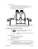
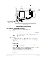
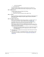
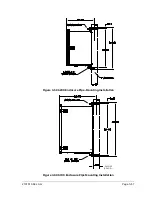
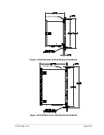
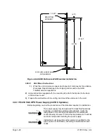
3.25 ENC82L Optional Catalytic Heater Installation
The following procedures describe the steps for installing a
catalytic heater for the environmental enclosure.
Verify the heater and fittings are approved for the classification
rating of the area of installation.
These instructions are only applicable to the large
environmental enclosure. In the small environmental
enclosure the catalytic heater is already installed.
3.25.1 Materials
•
Catalytic heater (installed at the factory)
•
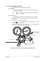
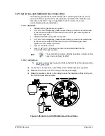
Thermostat assembly with temperature probe
•
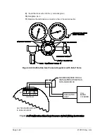
Regulator assembly with shut-off
•
T assembly
•
Tubing
•
Filter/drain assembly
•
Temperature probe mounting clip
•
Teflon
®
tape
•
¼” male pipe connection from external gas source to catalytic heater. Materials
for gas source are not be provided by Totalflow. Quantities and materials to be
determined by the technician based on installation and local codes.
•
DC power source wiring. Materials for external power source for electrical
preheat wiring are not provided by Totalflow. Quantities and materials to be
determined by the technician based on installation and local codes.
3.25.2 Instructions
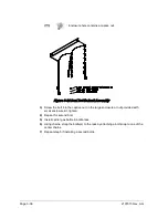
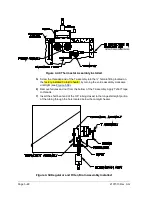
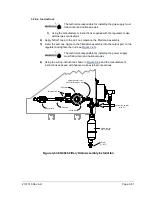
1)
Locate the installed catalytic heater on the rear of the environmental enclosure
(see
2)
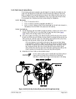
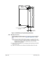
Remove the protective end cap from the catalytic heater input fitting, if required.
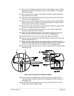
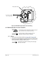
3)
Apply Teflon
®
tape to threads of the male end of the T assembly (see
).
4)
Screw the threaded end of the T assembly into the ¼” female fitting located on
the factory-installed catalytic heater, by turning the entire assembly clockwise
until tight (see


