2101510 Rev. AG
Page 3–45
3.24 Vent Lines Connections
The following procedure provides general steps for connecting the external vent
lines from the respective output ports on the feed-through assembly. When the
NGC is installed in the environmental enclosure, the sample vent line must vent
outside of the enclosure. Other installations may only require short lines. Follow
the requirements of national and local codes during this installation.
3.24.1 Materials
•
4 ea. 1/16” ferrule and nut
•
4 ea. 1/16” SST vent tubing (supplied with NGC) or
•
4 ea. 1/16” SST tubing (amount to be determined by the technician based on
the distance from the NGC to the external vent location)
3.24.2 Instructions
1)
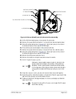
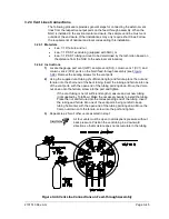
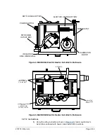
Locate the gauge port vent (GPV), sample vent (SV)), column vent 1 (CV1) and
column vent 2 (CV2) ports on the NGC feed-through assembly (see
). Remove the sealing screws for the vent ports.
2)
Using the supplied vent tubing (if sufficient length) and ferrule, place the nut and
ferrule onto the short end of the bent tubing. Insert the tubing and ferrule into one
of the vent ports, with the open end of the tubing pointing down. Move the Valco
nut down onto the ferrule, screw into the port and tighten.
If the vent tubing is not of sufficient length, measure and cut new tubing
(not supplied by Totalflow). Make the necessary bends to install the tubing.
Place the nut and ferrule onto the corresponding end of the tubing. Insert
the tubing and ferrule into one of the vent ports, being careful to keep
tubing horizontal, with the open end of the tubing pointing down. Move the
Valco nut down onto the ferrule, screw into the port and tighten.
3)
Repeat step 2 for all other vents as listed in step 1.
All four vents must be open to atmospheric pressure without
back pressure. Position the vent tubing in a downward
direction so that moisture does not accumulate in the tubing.
Figure 3-46 Vent Line Connections on Feed-through Assembly

