


2TLC010088M0201
Rev.A
8
4
Installation and maintenance
Installation
1.
The installation of all ABB Electrification safety dual interlock switches must be done in
accordance with a risk assessment for the individual application. Installation must only be
carried out by competent personnel and in accordance with these instructions.
2.
M5 mounting bolts must be used to fix the switch and actuator; the tightening torque to
ensure reliable fixing is 4.0 Nm. To prevent loosening of the switch after installation, always fix
the M5 mounting bolts with a thread-locking compound or secure using self-locking nuts.
Tightening torque for the lid screws, conduit entry plugs and cable glands must be 1.5 Nm to
ensure IP seal.
Only use the correct size gland for the conduit entry and cable outside diameter.
Tightening torque for the connection terminal screws is 0.7 Nm, max conductor size is 1,0 mm
2
.
The switch head position can be selected by removing the actuator, loosening the four head
bolts, and then rotating the head to the position required. Re-tighten the head bolts and then
check actuator insertion and withdrawal.
Tightening torque for the head bolts is 1.5 Nm.
Do not mount adjacent actuators or switches closer than 100 mm.
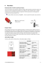
3.
Always fit a mechanical stop to a guard used without a slide bolt or rotary handle
accessory to prevent damage to the front of the switch.
Set the actuator gap to 3 mm when the guard is closed and against the stop (see
illustration).
Use alignment guides to ensure that the actuator enters the switch without
interfering with the sides of the aperture.
Ensure access to at least one of the manual release points.
Always fit the aperture plug to the unused entry aperture to prevent debris entering the switch
mechanism.
Caution!
Make sure the
Manual unlock function
screw is in “Locked” position before putting
the cover back on.
4.
After installation check operation of all control circuits and the locking function. For
applications with a run-down time after turning off power, ensure that the correct time delay
has elapsed before energizing the solenoid.
Warning!
All the safety functions must be tested before starting up the system.
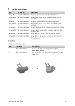
Note
: 8 actuator entry positions
rotatable head
Summary of Contents for MKey RFID Series
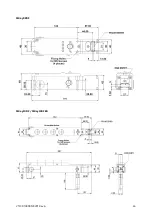
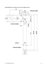
Page 15: ...2TLC010088M0201 Rev A 15 Dimensions MKey9RF MKey8RF ...
Page 16: ...2TLC010088M0201 Rev A 16 MKey8ZRF MKey10RF MKey10RFER ...
Page 18: ...2TLC010088M0201 Rev A 18 MKey10RF ER Die cast handle same for Left and Right versions ...
Page 20: ...2TLC010088M0201 Rev A 20 Slilde bolt MKey10RF ER same for Left and Right versions ...
Page 25: ...2TLC010088M0201 Rev A 25 9 Declaration of conformity ...
Page 26: ...2TLC010088M0201 Rev A 26 ...