


641P026-008
HMB-8 / HMB-8.7 Mechanism
©
(formerly HMB-11)
Page 7
4 November 2005
3
Principles of Operation
The HMB-8 mechanism uses the principles of hydraulics
to compress and charge the disc spring assembly. Hy-
draulic oil is transferred from a low pressure reservoir
97605 (Fig. 1) to a high pressure reservoir by a pump motor
51002 (Fig. 1) and pump element 51014. The high pres-
sure oil is used to compress the disc spring assembly with
the accumulator pistons. The disc spring assembly 51008
(Fig.1) acts as an energy storage system. During breaker
operation, stored energy is consumed and the disc spring
assembly discharges accordingly. The pump motor limit
switch (Fig.4) actuates and the pump motor automatically
re-charges the disc spring assembly. Principles of the
OPEN and CLOSE operations are described in the follow-
ing sections:
• Section 3.1 CLOSE operation
• Section 3.2 OPEN operation
3.1
CLOSE Operation
The front side of the drive piston 51012 (Fig. 2) is always
under hydraulic pressure when the disc spring assembly
51008 is charged. In the OPEN position, the back side of
the drive piston is at low pressure.
On actuation of the close pilot valve 51004 (Fig. 2), the
changeover valve 51006 moves to the orientation shown in
the CLOSE position illustration of Figure 2 allowing high
pressure hydraulic oil to flow on the back side of the drive
piston. Although there is high pressure on the front side of
the drive piston, the drive piston travels in the CLOSE
direction because the surface area on the back side of the
drive piston is greater than the surface area on the front side
of the drive piston, creating a net force in the CLOSE
direction.
A low pressure interlock 51016 (Fig. 9) prevents the drive
piston 51012 (Fig. 2) from drifting into the OPEN direction
in the event of very low system pressure. This interlock is
provided when required by the breaker type.
3.2
OPEN Operation
On actuation of the open pilot valve(s) 51005 (Fig. 2), the
changeover valve 51006 moves to the orientation shown in
the OPEN position illustration of Figure 2. High pressure
hydraulic oil flows from the back side of the drive piston
51012 and is released into the low pressure reservoir
97605 (Fig.1). The constantly present high pressure oil on
the front side of the drive piston propels the piston into the
OPEN position.
3.3
Over-Pressure Relief Device
The HMB mechanism is equipped with a pressure relief
valve 51045A (Fig. 2) to prevent damage or catastrophic
failure of components due to over-pressurization. Should
an over-pressure hydraulic situation occur because of a
pump motor failing to stop, the pressure relief valve 51045A
(Fig. 2) will prevent damage by automatically releasing
high pressure oil into the low pressure reservoir 97605
(Fig.1).
4
Mechanism Maintenance
Major
maintenance involving disassembly of the HMB-8
mechanism can be performed by factory-trained represen-
tatives or by trained customer technicians. Major mainte-
nance is performed only if a problem arises.
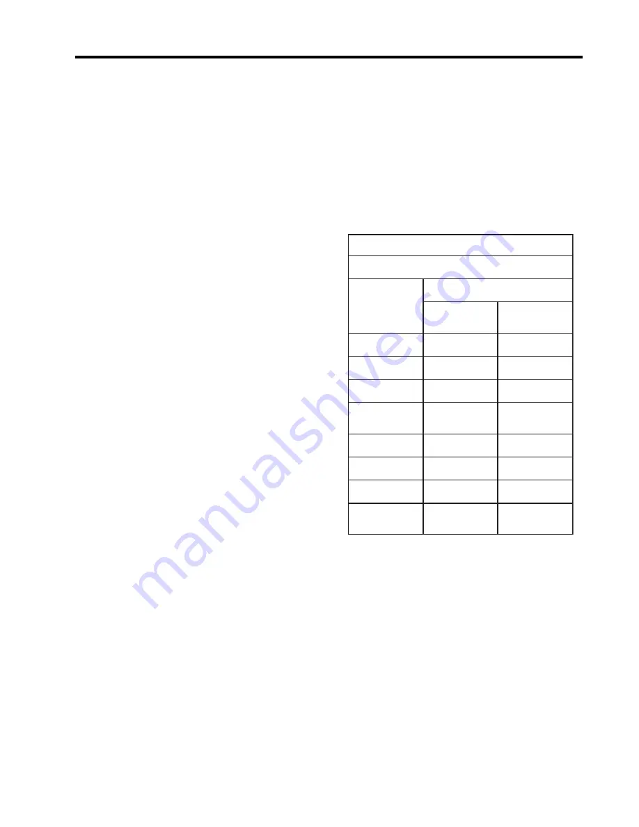
To ensure proper operation, the HMB mechanism requires
routine
maintenance checks every year. Addtional mainte-
nance checks are required after every 5 years of service.
Table 1 lists a routine maintenance check schedule for the
HMB mechanism.
1
e
l
b
a
T
s
k
c
e
h
C
e
c
n
a
n
e
t
n
i
a
M
e
n
i
t
u
o
R
k
c
e
h
C
o
t
m
e
t
I
y
c
n
e
u
q
e
r
F
y
l
r
a
e
Y
y
r
e
v
E
s
r
a
e
Y
5
l
e
v
e
L
li
O
k
c
e
h
C
k
c
e
h
C
n
o
it
i
d
n
o
C
li
O
-
-
-
-
k
c
e
h
C
s
e
h
s
u
r
B
r
o
t
o
M
k
c
e
h
C
k
c
e
h
C
-
a
s
n
e
d
n
o
C
-
it
n
A
r
e
t
a
e
H
n
o
it
k
c
e
h
C
k
c
e
h
C
g
n
ir
i
W
-
-
-
-
k
c
e
h
C
s
l
a
n
i
m
r
e
T
-
-
-
-
k
c
e
h
C
r
e
t
n
u
o
C
t
r
a
t
S
k
c
e
h
C
k
c
e
h
C
e
r
a
w
d
r
a
H
s
s
e
n
e
t
h
g
i
T
-
-
-
-
k
c
e
h
C
DANGER
Mechanisms pose inherent hazards
associated with high energy equip-
ment having rapidly moving parts
and electrical components. Only
qualified personnel possessing a
full understanding of this equipment
should operate or service this equip-
ment. Be careful of limbs and ex-
tremities when working around this
equipment as they may become en-
tangled in moving parts.
Summary of Contents for Mechanism HMB-8
Page 2: ......
Page 5: ...641P026 008 HMB 8 HMB 8 7 Mechanism formerly HMB 11 Page 5 4 November 2005 ...
Page 19: ...641P026 008 HMB 8 HMB 8 7 Mechanism formerly HMB 11 Page 19 4 November 2005 NOTES ...
Page 33: ...641P026 008 HMB 8 HMB 8 7 Mechanism formerly HMB 11 Page 33 4 November 2005 NOTES ...