


6
L ST 20 0 |
U LT R A S O N I C L E V EL T R A N SM I T T ER | C I/L S T 2 0 0 - EN R E V. C
7
L ST 20 0 |
U LT R A S O N I C L E V EL T R A N SM I T T ER | C I/L S T 2 0 0 - EN R E V. C
NOTICE
After an interval of several weeks, increased force will be
required to remove the housing cover. This situation is
normal; it is caused by the type of gasket used
After power-on, there would be 50s or less before LST200
fully started
8 Configuring using the Easy Setup
menu
After start-up, the indicator shows the current PV value and
percentage. You can push the right button to enter the main
menu and the left button for diagnostic information if errors
existed. In the Main menu, use left button for scrolling and right
button for entering
The most common configuration parameters are summarized
in the Easy Setup menu, including:
Language
English, Chinese
Operation Mode
Level Mode, Flow Mode, Volume Mode,
Distance
Mode
Length Unit
m, cm, mm, feet, inch
Empty Distance
0 to 8000 mm
Span
0 to 8000 mm
Blanking
350 to 8000 mm
Max change rate
0 to 720 m/h
Tips:
• After you set the empty distance and span, the 0% (4 mA
point) and 100 % (20 mA point) will link to 0mm (bottom of
the tank) and the span value you entered. If you want to
change the mapping, go to the “Input/Output” menu.
• Max change rate can help you ignore the sudden level change
(the change rate larger than the setting). This could be used
when unexpected obstacles and noise randomly occur. Be
careful that the real change might be ignored if the value was
set too small. Disable this function by setting the value to ‘0’ .
• For your reference: Very Slow: <1 cm/min ,Slow: <5 cm/min
,Medium: <25 cm/min ,Fast: 1 m/min ,Very Fast: <5 m/min
• The blanking is better to be set at a larger value to filter
unexpected noise.
Your LST200 instrument comes configured with certain default
parameters, but you still need to select certain options and set
specific values for your instrument to work as you expect.
To start the configuration, you need to understand the
parameters below:
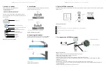
Figure 7: LCD and menu
Figure 6: Typical installation and key parameters
Main Menu
Easy Setup
Device Inf
o
Device Setup
Display
Input/Output
α
F
B
L
(S)
E
D
r
B
E
F
D
L
α
Blanking area
Should be set ≥ 350 mm, signals
within this area would be ignored
Distance from sensor surface
Max. 8 m, set according to the
distance from tank bottom to
sensor
Level from tank bottom
(defined by empty distance) sensor
Set according to users’ 100%
output point, suggest leave a
safety distance “S” from blanking
area
Detection range reference, avoid
obstructions (Filling water,
switches, weld seam) in thisrange.
Reference for best
performance:distance from tank
bottom to sensor
D=8 m, r=694 mm
D=5 m, r=431 mm
D=2 m, r=169 mm
D=6 m, r=519 mm
D=4 m, r=344 mm
D= 1 m, r=81 mm
Distance
Empty distance
Level
Full range (Span)
Emitting angle 10°
9
Configuring using the ABB FIM with
LST200 FDI package
ABB’s Field Information Manager (FIM) software employs Field
Device Integration (FDI) technology and is equipped with
high-performance and innovative graphical user interface that
helps technicians to effectively work with the process
instrumentation.To connect the PC with LST200, a specially
designed interface cable should be ordered from ABB with
part number : 3KXL065113U0100
Interface cable
Figure 8: Interface cable connection
Power supply
Scan for video of installation and setup