

2105836-001 (AB)| LEVELMASTER 7100 | 8/2019
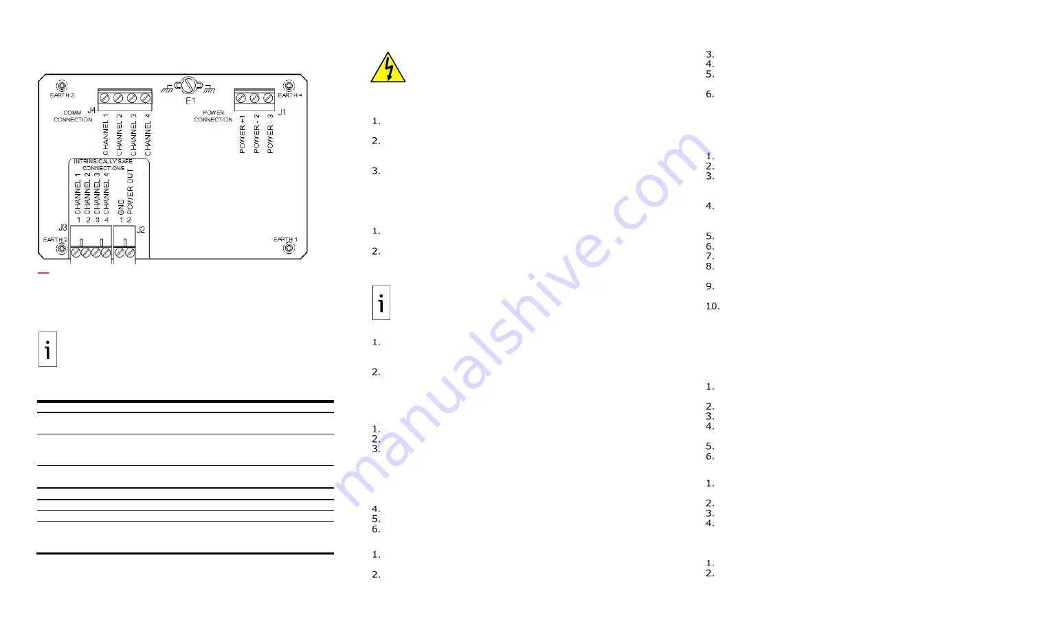
Figure 7: Totalflow CSA-certified barrier board (hazardous
locations)
LevelMaster 7100 Quick Start
This guide includes basic steps for a new general-purpose
installation and setup in an unclassified area. For hazardous
location installations refer to online publications.
IMPORTANT NOTE:
Installations may involve single or multiple
interconnected units and mixed board types. For multi-unit
installations, determine intermediate and last units in the
connecting bus to terminate the RS-485 bus correctly.
Setup requirements
Table 1: Requirements per board type below.
Board number
2104836-001
2018546-005
RS-485 termination
Through software
Through onboard
termination pins
Float types
All types including
batteryless floats
(kit 2018392-017)
All types except
batteryless floats
MasterLink
version
2.0 (required for
batteryless floats)
2.0 or earlier
For setup (not for permanent connection)
RS-485 cable adapter
2100250-002 2100250-001
RS-485-to-RS-232
bl
2100241-005 2100241-002
RS-232-to-USB
converter
Digi
®
Edgeport/1 USB Converter
for laptops without RS-232 ports. Software drivers
are required (1801382-001).
DANGER – Bodily injury:
Configure the LevelMaster before
inserting into the tank. Follow your company policies and safety
guidelines to complete installation.
Install LevelMaster components
With the sensor positioned and supported horizontally:
Wrap Teflon
®
tape, or another sealing material, around cord
connector and tank port bushing threads.
Slide the components into the bottom of the LevelMaster in the
following order: Cord connector, tank port bushing, floats. If using
two floats, slide the oil float on first (see Figure 1.)
Slide and tighten the float clamp at 1 inch above the bottom of
the casing.
Assemble local communication cable
Connect the converter cable and adapters based on board type
and ports available on the laptop (see Figure 2.)
Connect the RS-485 cable adapter to the RS-485-to-RS-232
converter cable.
If using a laptop without RS-232 ports, connect the RS-485-to-
RS-232 converter cable to the RS-232-to-USB converter.
Connect to the LevelMaster
IMPORTANT NOTE:
Ensure MasterLink 2.0 is already installed in
the PC or laptop. MasterLink has context-sensitive online help.
Click
Help
on the screen of interest for details.
To configure the LevelMaster, connect to the electronic board:
Remove cover from the electronic enclosure and pull the
electronic board up gently without disconnecting it from the
sensor assembly.
With a small slotted screw driver, remove the connectors from the
onboard communication and power terminals. Save these
connectors for wiring.
Use the local communication cable to connect the
laptop to the electronic board.
Insert the red wire connector to the cable assembly battery.
Start
MasterLink
on the laptop.
At the main screen, add a location for the new unit:
a.
Right-click inside the screen (white area) and select
Add
New Location
.
b.
Enter up to 25 characters for a location name.
c.
Click
OK
to save the name. Verify that the location displays.
d.
Select the new location (ensure it is highlighted).
Click the
Comm. Port
drop-down list.
Select the laptop communication port used.
Leave the Baud Rate at 9600 (factory default).
Verify communication
Click
Setup LevelMaster
. The New LevelMaster Setup window
displays.
Select
I have only one LevelMaster connected to
communication port and I want to set it up.
Click Setup LevelMaster.
When prompted to add the LevelMaster to the list, click
Yes
.
When prompted for the LevelMaster name, type a unique name of
up to 15 characters and click
OK
.
Observe the messages displayed on the monitor screen. Verify
that communication is successful (100% success).
Set up unit with generic configuration
MasterLink 2.0 includes generic configuration files for different
sensor lengths. To load one of these files to the LevelMaster:
Click the
Upload/Download
tab.
Under Send data to the LevelMaster, click
Browse […]
.
In the browser, navigate to the applicable default files folder. For
example, C:\Program Files (x86)\ABB\MasterLink\DefaultDat\7.0
Head board.
Locate the file for the correct length of sensor and click
Open
. For
example, for a 20 ft sensor, select the "Dual_20ft_batteryless.dat"
file.
Click
Download Data to LevelMaster
.
Click
OK
when the download is complete.
Click the
Setup
tab.
Type a unique ID in the New LevelMaster ID field and click
Set
New ID
.
Configure the baud rate for communications. Baud rates for all
connecting units, including the controller, must match.
Configure termination if the LevelMaster is the only unit installed
or is the last unit on an RS-485 bus. Leave intermediate units with
factory default configuration.
Configure RS-485 bus termination
Perform this procedure only for boards with part number
2104836-001. For legacy boards, set termination jumpers
onboard (see Figure 3.)
Click the
Monitor
tab and select the
Add Advanced Setup
tabs.
Additional tabs display.
Click the
More items
tab.
Select
Show memory map
.
Scroll down, locate, and double-click the
844-memory address
or "
RS-485 bus termination
". The default value is 0.
When the edit box displays, change the value to
1
.
Click Send New Value.
Install the LevelMaster into the tank
Remove the local connection cable from the board. Position the
board inside the enclosure.
Reinstall and secure the enclosure cover.
Slide components to the bottom.
Lift and insert the LevelMaster into the tank.
Wire the LevelMaster electronic board
Refer to Figure 4 or Figure 5 for wiring.
Remove enclosure cover to expose the board again for wiring
Wire units and controller for communication and power.
Insert wired connectors on units, reinstall, and secure cover.