background image

IB 6.2.11.1-2C 

Page 13 

ABB 


Arc Chutes


a. Remove the two arc chute mounting screws and 
retainer moldings.  Lift arc chute (1, Figure 1) up and 
draw out.  
 
b. Inspect for breakage of the arc chute frame or 
retainer molding.  Check for presence of foreign 
particles such as chips of metal.  Discoloration and 
carbon build-up are normal in an arc chute that has 
seen service, but the arc plates should not be 
significantly worn, as indicated by severe warping of the 
cut-out pattern. 
 

Insulation Structure 

 
Insulated parts should be checked for damage.  Dust 
and dirt should be removed by air or wiped with a clean, 
lintless cloth.  Do not use any oil based solvents.  Spray 
solvents vary as to type and should not be used.  The 
moldings at the rear of the breaker must be kept clean 
to avoid dielectric problems.  Wipe dust away and blow 
out with clean, dry, compressed air.  Additional steps 
must be taken if dust accumulation continues to be a 
problem. 
 

MPSC-2000 Trip Device Removal and Installation 

 
1. Remove the two nylon screws which retain the trip 
system harness plug to the MPSC-2000 device.  Retain 
for re-use.  If the breaker has the Voltage Interface 
Module (VIM) option, disconnect the four-pin plug from 
the trip unit. 
 
2. Remove the six screws holding the breaker top shelf 
and remove the shelf with the MPSC-2000 unit 
attached. 
 
3. To reinstall, reverse the above procedure.  Be sure to 
secure the DB-25 plug in the MPSC-2000; 

energizing 

the breaker with this plug removed or not secured 
will result in serious damage to the device and 
perhaps injury to nearby personnel

.  In addition, the 

breaker will not be able to provide circuit protection. 
 
(NOTE:  Metallic screws must not be used to retain the 
trip system harness.  Should a metallic screw fall into 
the trip system, serious damage can result.) 
 

Electrical Components (EO Breakers Only)


1. Rack the circuit breaker to the “TEST” position.  
Make sure the closing springs are charged. 
 
2. Operate the local (if installed) or remote electrical 
close push button as applicable to close the circuit 

breaker.  This will confirm operation of the close coil. 
 
3. While maintaining the close signal, trip the circuit 
breaker with the shunt trip.  The Solid State Control 
Device (SSCD) should prevent the reclosing of the 
circuit breaker until the close signal is removed and 
then re-applied.  SSCD replacement may be required if 
it does not perform as indicated. 
 
4. During the previous test, electrical operation of the 
shunt trip and the spring charging motor is confirmed.  
Malfunction of either requires repair or replacement. 
 

Contacts 

 
a. Remove dirt or grease on contacts with a clean, 
lintless cloth. 
 
b. Discoloration of the main contacts does not 
necessarily indicate damage.  However, this condition 
may be removed by opening and closing the circuit 
breaker under no-load conditions. 
 

Contact Pitting 

 
A moderate amount of pitting will not interfere with the 
operation of the arcing contacts.  Should it be 
necessary to dress the arcing contacts to remove small 
burrs, cover the mechanism with a cloth.  Follow the 
contour of the contacts with light wipes of a fine file and 
do not attempt to eliminate pitting entirely.  When 
finished, remove cloth and wipe off any remaining dirt or 
filings. 
 
Should the main contacts show more than moderate 
pitting, check the contact pressure. 
 

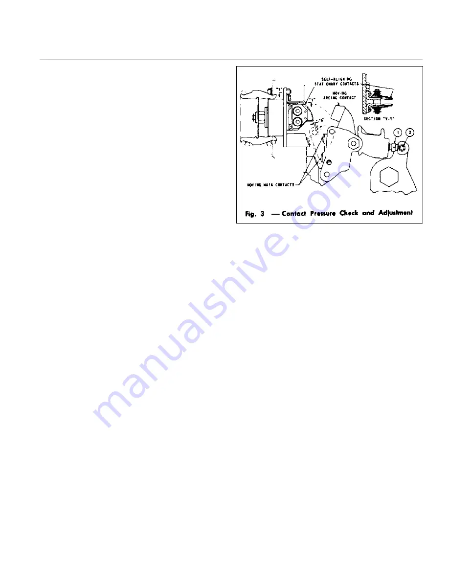
Contact Pressure Check and Adjustment (See 

Summary of Contents for K-Line Plus KP-32

Page 1: ...IB 6 2 11 1 2C Installation Maintenance Instructions Low Voltage Power Circuit Breaker K Line Plus Types KP 32 KPE 32 KP 40 and KPE 40 ABB ...

Page 2: ...CE FOR EO BREAKERS 10 CLOSING SPRING OPERATION 11 INSTALLATION INITIAL TESTING REMOVAL 11 Installation 11 Checking Breaker Operation in TEST 11 Checking Breaker Operation in CONNECTED 11 Manual Closing Operation 12 Circuit Breaker Removal 12 MAINTENANCE AND ADJUSTMENTS 12 Periodic Maintenance Inspection 12 Arc Chutes 12 Insulation Structure 13 MPSC 2000 Trip Device Removal Installation 13 Electric...

Page 3: ...inal carton covering with waterproof paper and sealing to prevent infiltration of dirt Where conditions of high humidity prevail the use of heaters is recommended BASIC HANDLING Once the circuit breaker has been unbolted and removed from its shipping carton it should be turned to the upright position and placed on a flat surface to avoid damage to breaker parts For safety all handling in this posi...

Page 4: ...ip indicator is pushed in the circuit breaker mechanism can then be operated to close the circuit breaker contacts Padlocking Device Figure 1 Item 13 All K Line Plus circuit breakers are equipped with means of padlocking the circuit breaker mechanism in a trip tree position This is accomplished by the use of a locking plate to maintain the manual trip button in a tripping direction when the lockin...

Page 5: ...ional 10 Manual Trip Button 11 Drawout Lever 12 Manual Close Lever 13 Padlock Hasp 14 Motor Disconnect Switch EO only 15 Automatic Trip Indicator 16 Manual Charging Handle Optional 17 Position Indicator Label 18 Spring Charging Motor EO only 19 Racking Cam Rollers 20 Electrical Trip Close Buttons Optional Not Shown Figure 1 Typical Electrically Operated K Line Plus Circuit Breaker 1 19 3 4 5 18 17...

Page 6: ... 4 3 TC 1 51 2 a AS Trip Control Device 5 P18 A5 P4 P20 P8 2 P6 A2 P2 P19 P22 P1 P10 Solid State 3A 1 3 A3 P17 4 Trip A4 2 P5 4A 1 7 P9 P3 80 19 17 15 A14 A18 A16 23 21 A22 A20 14 18 16 20 22 A15 A21 A19 A17 A23 5 6 AS a 10 AS 9 a 12 AS 11 b 14 AS 13 a 16 AS 15 b 53 65 CSCS CSCS 64 63 56 57 NO C C NO B21 32 31 B22 B13 B9 B11 B7 34 32 36 B15 B17 B19 38 40 42 44 19 17 18 a AS 20 21 23 b AS 22 AS a 2...

Page 7: ...5 Not Used supplied with the breaker for pin out assignments 6 The assignments for pins B3 B6 will differ depending on whether the DESP option has been supplied See the MPSC 2000 schematic supplied with the breaker Notes 1 These assignments are provided for reference only and may be changed due to special requirements Some pins or plugs may not be present on all breaker configurations See the brea...

Page 8: ...ical closing functions of the breaker The anti pump feature of the SSCD prevents a second electrical closing until the first closing signal is released For example if the breaker is closed electrically and the signal is maintained the SSCD will not permit the breaker to be closed electrically again after a trip until the electrical close signal is released Shunt Trip The shunt trip is standard on ...

Page 9: ...the tripping energy from the primary current passing through the circuit breaker without the need for any additional power supply An external 9V battery is supplied to permit the user to access the MPSC 2000 s menus The battery is not required for correct operation of the trip device The battery will last only about 1 2 hours of actual use so the switch to this battery should be left in the off po...

Page 10: ...npacked from the factory may have the target displayed as a result of the factory testing performed on the breaker prior to shipping This target will reset when the circuit breaker is closed and sufficient primary current is flowing Continuous monitoring of the microprocessor function is programmed into the MPSC 2000 Watchdog circuits guard against the possibility of microprocessor disfunction due...

Page 11: ...See Figure 1 The circuit breaker must be in the OPEN position the racking crank 8 Figure 1 when inserted in opening is rotated counterclockwise until the racking cam roller 19 is rotated down into a 45 angle and the motor disconnect switch 14 for electrically operated circuit breakers is in the OFF position NOTE Lever 11 must be pushed down to permit the rotation of crank 8 Open compartment door a...

Page 12: ...nd close door MAINTENANCE AND ADJUSTMENTS SAFETY NOTES When it is necessary that the charging springs be charged or the circuit breaker be closed make sure to stay clear of operating parts Breakers shouId be withdrawn to TEST position for checking the breaker operation For further inspection adjustments cleaning or replacement of parts the circuit breaker should be withdrawn from the cell and move...

Page 13: ...dition the breaker will not be able to provide circuit protection NOTE Metallic screws must not be used to retain the trip system harness Should a metallic screw fall into the trip system serious damage can result Electrical Components EO Breakers Only 1 Rack the circuit breaker to the TEST position Make sure the closing springs are charged 2 Operate the local if installed or remote electrical clo...

Page 14: ...mp charging handle until the circuit breaker closing springs are heard to snap into the charged position also check the indicator 6 c Remove screw shift the shutter to the left and insert the spring retainer bracket so that its tips fit into the closing springs and its flanges fit into the holes in the closing spring guides NOTE Shutter cannot be opened unless breaker drawout mechanism is in the D...

Page 15: ...s the primary latch roller from moving to the left and opening the breaker If none of the various trip devices are acting on the tripper bar or the auxiliary latch tripper to open the breaker or to prevent the breaker from closing and the breaker still will not close then the following adjustment should be made a Turn screw 1 Figure 5 down to insure that the secondary trip latch will hold the seco...

Page 16: ...s one equal to the maximum frame continuous current rating of the breaker mounted current sensors and one equal to half the frame rating For example on an 4000A breaker with 4000A sensors the MPSC 2000 rating can be set to 4000A or 2000A When the rating is changed other available settings are scaled accordingly thus the term Range Selection Instantaneous or Short Time Threshold Test 1 Either disab...

Page 17: ...ly from twice to four times the Range Selection and that the trip curve is fixed and does not vary with pickup settings 7 Set test current so that it represents 1 5 times the ST Pickup setting Delays should be as shown in Table 4 Ground Trip Delay Tests Ground Trip Delay tests are performed by injecting current through a single phase of the breaker which appears to be a ground fault to the trip de...

Page 18: ...insulation to withstand overvoltages 2 A 60 cps alternating sinusoidal voltage rms value equal to the specific voltage shall be used All voltages used in the dielectric withstand test shall be measured in accordance with ANSI Measurement of Voltage in Dielectric Tests C68 1 3 Duration Of Test The dielectric test voltage shall be applied for a period of 60 seconds The duration of the test may be on...

Page 19: ...a short circuit ii Motors that have been in service may fail dielectric due to a normal accumulation of debris from the commutator Cleaning the motor will restore dielectric integrity iii Do not perform dielectric testing on the solid state trip system RENEWAL PARTS ABB recommends only those renewal parts be stocked that will be required to insure proper and timely maintenance of the breaker ...

Page 20: ...IB 6 2 11 1 2C Page 20 ABB NOTES ...

Page 21: ...IB 6 2 11 1 2C Page 21 ABB NOTES ...

Page 22: ...IB 6 2 11 1 2C Page 22 ABB ABB Inc P O Box 100524 Florence South Carolina 29501 Phone 843 413 4700 Fax 843 413 4850 ABB ...

Reviews: