IB
6.1.12.1-1C
2
8
ABB
31 29 27 25
28
32 30
26
20
24 22
18
19
23 21
17
12
16 14
10
11
15 13
9
4
8
6
2
3
7
5
1
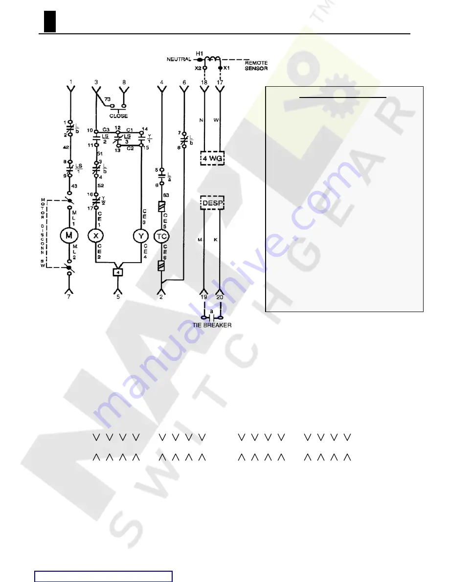
Schematic Symbol Legend
M = Closing Spring Charging Motor
X = Close Coil
Y = Anti-pump Lockout Coil
TC = Shunt Trip Coil
LS = Limit Switch
CE = Coil Lead
x1, x2 = Sensor terminal markers
H1 = Sensor orientation marker
L = Left end mounted auxiliary switch bank
a = Auxiliary Switch Contact: normally open when
breaker is open
b = Auxiliary Switch Contact: normally closed when
breaker is open
r = Alarm Switch Contact: closes on automatic trip,
manually reset (alarm circuit not illustrated)
s= Alarm Switch Contact: opens on automatic trip,
manually reset (alarm circuit not illustrated)
Y/1 = Y contact normally open
Y/2 = Y contact normally closed
LS/1, LS/3 = LS contact normally closed when
closing springs are discharged
LS/2 = LS contact normally open when closing
springs are discharged.
Figure A1. Schematic of a Basic Control Circuit for an EO circuit breaker.
Illustrated for a breaker in the
OPEN and SPRINGS DISCHARGED state. The basic circuit includes a closing spring charging motor, local
electric push button close, control relay device (close and lockout coils), and a shunt trip device. Also shown:
optional four wire ground and double-ended substation applications.
Figure A2. Arrangement of Secondary Disconnects and Contact Identification.
Viewed
from the rear of the circuit breaker. Depending upon the installed options, a circuit breaker
may be equipped with all four pair of secondary disconnects as illustrated.


