ABB JDF300 Operating	 Instruction Download Page 11

J DF 3 0 0  |

  FI EL D I N D I C ATO R  |  O I/J D F 3 0 0 - EN R E V. B

11

Test  voltage  withstand  capability  can  no  longer  be  ensured             
when this protective circuit is used.

7   Electronic Board

Fault protection

The JDF300 FF electronic implements a special circuitry for the 
fault current protection. Whenever a fatal failure occurs and the 
current consumption increase over the 20 mA, this circuitry 
provides to disconnect the device from the bus, in order to 
preserve the rest of the bus that, otherwise, risks to drop down 
all the other connected devices.
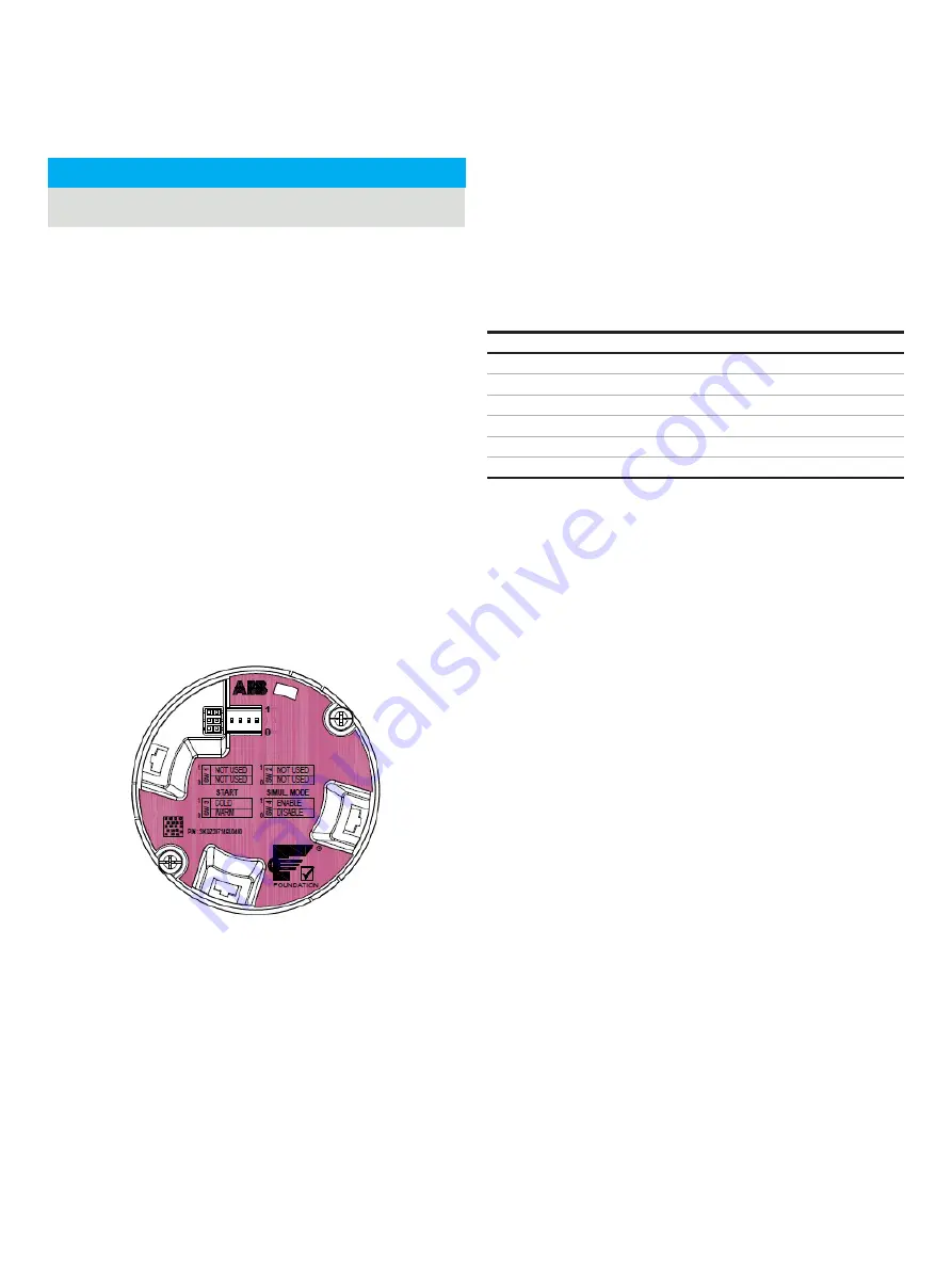
On board switches

On the electronic unit under the display there are 4 dip switches 
with the following functionality:

•  Switch 1 and 2

 are reserved for future use 

•  Switch 3 

selects the start mode between COLD and  WARM-

START UP. When in ON position and COLD start is selected, it 
means that when a new power cycle is executed the device 
will  be  set  to  a  predefined  basic  configuration.                                                                               
Some parameters of the HMITB, RB and MAO blocks are 
written to a well defined value while all the other function 
blocks are set to their FF standard default (“Initial Values”).

Figure 7   Electronic board view

After the Cold Start the JDF300 is ready to work displaying the 
value of MAO_IN1 (input 1) with its default Subtag and unit code 
while the quality status is displayed as textual format. Refer to 
the Block’s table at the end of this manual to see which 

parameters are forced to a default value by the Cold Start-up 

function. They are in Bold/italic/underlined (pink color).

The basic parameters set by the Cold start up are the following:

Cold start-up condition

MAO_Channel

IN1 (1)

HMITB_IN1_SUBTAG

“Input 1”

HMITB_IN1_Unit

“none”

HMITB_IN_ENABLED

Only IN1 enabled (00000001)

HMITB_SEQUENCE

Disabled (1 – OFF)

HMITB_NUM_STATUS_ENA

Status byte in Text format (1)

Switch 4

 selects the simulation mode which is a mandatory 

requirement for FF devices.
JDF300O can simulate only diagnostic conditions writing the 
error to be simulated into 

“RB_FD_SIMULATE” (index 67)

However, this writing has effect only if the HW switch4 has 
been previously moved in ON position (SIMUL MODE ENABLED).

IMPORTANT

Summary of Contents for JDF300

Page 1: ...undation Fieldbus indicator provides remote visibility for up to 8 variables subscribed from the bus publisher subscriber or directly written by the Host client server Each individual variable input t...

Page 2: ...General risk for JDF300 used in zone 0 8 Installing JDF300 field indicator 8 Bracket mounting 8 Securing the housing cover in flameproof areas 9 6 Field indicator wiring 9 Cable connection 9 Supply re...

Page 3: ...c 41 OUT status 41 Troubleshooting 41 Control Selector Function Block CS 42 Overview 42 Block diagram 42 Description 42 Equations 42 Configuration hints 42 Block mapping 43 Diagnostic 44 OUT status 44...

Page 4: ...engineering standards regarding maintenance and use of adequate safety systems For safety reasons ABB draws your attention to the fact that only sufficiently insulated tools conforming to DIN EN 6090...

Page 5: ...ly For information on permissible ambient conditions for storage and transport see Technical data Although there is no limit on the duration of storage the warranty conditions stipulated on the order...

Page 6: ...on concerning product code output signal tag and product serial number see Ref A Please refer to this number when making enquiries The Safety Marking plate provides information of Ex protection it is...

Page 7: ...ons carefully before proceeding Failure to observe the warnings and instructions may cause a malfunction or personal hazard Before installing the field indicator check whether the device design meets...

Page 8: ...db IIC T4 Gb Flameproof Canada Class I Zone 1 Ex db IIC T4 Gb Intrinsically safe Class I Zone 0 AEx ia IIC T6 T4 Ga US Class I Zone 0 Ex ia IIC T6 T4 Ga Canada Class I Division 1 Groups A B C D T6 T4...

Page 9: ...ent on leads can cause electrical shock Do NOT make electrical connections unless the electrical code designation agrees with the classification of the area in which the field indicator is to be insta...

Page 10: ...over when power is applied to the unit Run the cable through the cable gland and the open port Connect the two bus wires to the terminal and the terminal without taking care of their polarity Plug and...

Page 11: ...and MAO blocks are written to a well defined value while all the other function blocks are set to their FF standard default Initial Values Figure 7 Electronic board view After the Cold Start the JDF30...

Page 12: ...ver with Ex d 2 Attach the LCD display Depending on the mounting position of the field indicator the LCD display may be attached in four different positions This enables 90 or 180 rotations Retighten...

Page 13: ...identify the displayed measure Unit code of the displayed measure as a text of 8 characters The user can write the Variable TAG and its unit code of each of the 8 MAO Block inputs Refer to the parame...

Page 14: ...s could be taken in account The menu submenu name is displayed above in the LCD display The number line of the currently selected menu item is displayed in the upper right of the LCD display A scroll...

Page 15: ...vents the configuration data from being overwritten by unauthorized users If write lock is enabled the Z and S buttons are disabled When the JDF300 is write locked the lock symbol is displayed in the...

Page 16: ...unication or through the S button the Autoscrolling function is enabled While the HMI_IN_SEQUENCE is enabled ON the Z button stops its function until the HMI_IN_SEQUENCE is disabled again After the S...

Page 17: ...blinks the string Squawk When Squawk is enabled on the display it starts to blink the word Squawk till when the HMITB_SQUAWK parameter is disabled again or till when the user who find the device in t...

Page 18: ...arameters relating the NAMUR NE107 requirements are those with the prefix FD_xxx Each root error is mapped into one of the four NAMUR NE107 classifications Failure Maintenance Out of Specifications an...

Page 19: ...The SW4 of the electronics is in ON position enabling the Simulation Bit 6 Device Needs Maintenance Soon NV Mem Burn error Bit 11 Lost NV Data Electronic memory fail Bit 15 Out of Service The Resource...

Page 20: ...e first alert to become active will set the Active Status in the status parameter As soon as the Unreported status is cleared by the alert reporting task another block alert may be reported without cl...

Page 21: ...er 69 SPECIAL_RESTART Bit 11 AR pre setting After the selection of one or more blocks of this list is written to SPECIAL_RESTART then the operation is really executed writing the command Special Resta...

Page 22: ...display configuration While the Value and Quality Status are received from the selected MAO Input the Subtag and Engineering unit to display together with the value must to be configured inside this...

Page 23: ...t is generated by any change to the static data 8 BLOCK_ALM The block alarm is used for all configuration hardware and connection failure or system problems in the block The cause of the alert is ente...

Page 24: ...Number of power cycle 39 TOT_WORK_TIME Counter of how much time the device has been powered on expressed in days hours mins 10 Control Application Process CAP Blocks Multiple Analog Output Function Bl...

Page 25: ...it 0 Other MAO Not Scheduled Bit 1 Configuration Error MAO Channel 0 Uninitialized Bit 15 Out of Service 7 CHANNEL 0 Uninitialized Doesn t allow at the MAO to move out from OOS 1 8 INPUT n selection C...

Page 26: ...onfiguration error M080 005 Enable at least one input in the HMITB IN_ENABLED 30 Electronic Memory Fail Memory data corrupted Memory failed F RB Lost NV data F150 030 Electronic should be replaced as...

Page 27: ...r whose time constant is PV_FTIME The value is then shown as the PV which is used in conjunction with the SP in the PID algorithm A PID will not integrate if the limit status of IN is constant A full...

Page 28: ...edback so it must be set properly and never changed while in an automatic mode The setting of the option must also be used in calculating the limit state for BKCAL_OUT The output supports the feed for...

Page 29: ...calculated as a result of the block execution expressed in OUT_SCALE unit code Writeable only if MODE_BLK ACTUAL MAN 10 PV_SCALE The high and low scale values engineering units code and number of dig...

Page 30: ..._SCALE Unit Code 28 OUT_HI_LIM Acceptable value OUT_SCALE 10 Expressed in OUT_SCALE Unit Limits the maximum output value 29 OUT_LO_LIM Limits the minimum output value 30 BCAL_HYS 0 to 50 Default 0 5 E...

Page 31: ...be reported without clearing the Active Status if the subcode has changed 46 ACK_OPTION Used to set auto acknowledgment of the alarms 47 ALARM_HYS Alarm Hysteresis is the amount the PV must return wi...

Page 32: ...Mode of the RESOURCE BLOCK to AUTO mode The Block is not scheduled Design the FB Application correctly and download it to the devices The Block cannot be removed from IMAN mode Something wrong in the...

Page 33: ...ded to be used in a control path so it does not support control status propagation or back calculation It has no process alarms The block has 5 inputs The first two are dedicated to a range extension...

Page 34: ...he function equations The equation for each auxiliary input is the following t_i IN_i BIAS_IN_i GAIN_IN_i The flow compensation functions have limits on the amount of compensation applied to the PV to...

Page 35: ...h time a static parameter value S under Storage in the block is changed 2 TAG_DESC The user description of the intended application of the block 3 STRATEGY The strategy field can be used to identify g...

Page 36: ...iplied times IN_3 Bias 27 COMP_HI_LIM The high limit imposed on the PV compensation term Expressed in PV_SCALE Unit Code 28 COMP_LO_LIM The low limit imposed on the PV compensation term Expressed in P...

Page 37: ...configured to use it In this case the Status of the OUT is UNCERTAIN Otherwise the OUT Status id the worst of the inputs used in the calculation after applying the INPUT_OPTS Troubleshooting Problem P...

Page 38: ...figured and a bad status is passed to one of the inputs Logic is provided for handling uncertain and bad signals in conjunction with configured actions The intended application of this block is to pro...

Page 39: ...rage was used else set SELECTED to the number of the input with the middle value If SELECT_TYPE is Average compute the average of the remaining inputs and transfer the value to the output of the block...

Page 40: ...on the block 9 GRANT_DENY Options for controlling access of host computer and local control panels to operating tuning and alarm parameters of the block 10 STATUS_OPTS Options the user may select to a...

Page 41: ...to Good when the Selected Input Status is Uncertain Uncertain if Manual Mode The Status of the IS_OUT is set to Uncertain when the Mode is set to Manual Troubleshooting Problem Possible cause Solution...

Page 42: ...Control blocks that are not selected are limited in one direction only determined by the type of selector The value of each BKCAL_SEL_N output is the same as OUT The limits of back calculation output...

Page 43: ...N Bit 2 Use Uncertain as Good 11 SEL_1 First input value to the selector Expressed in OUT_SCALE Unit 12 SEL_2 Second input value to the selector 13 SEL_3 Third input value to the selector 14 SEL_TYPE...

Page 44: ...SEL_x output The BKCAL_SEL_x Status of the deselected inputs is set to Not Selected with the appropriate high or low limit set When the CS is in MAN no inputs are selected All the BKCAL_SEL_x status a...

Page 45: ...IEC TS 60079 31 1 Cleaning of the painted surface shall only be done in accordance with the manufacturer s instructions Explosion proof field indicator must be either repaired by the manufacturer or a...

Page 46: ...st be connected to a supply associated apparatus certified Ex ia The other marking part refers to the protection type used according to relevant EN standards and is valid also for IECEx as detailed in...

Page 47: ...application Db Equipment Protection Level About the applications this field indicator can be used in Zone 1 Gas classified areas continuous hazard About Dust application JDF300 is suitable for Zone 21...

Page 48: ...s field indicator can be used in Zone 2 Gas unlikely infrequent hazard About Dust application JDF300 can be used in Zone 22 unlikely infrequent hazard as it shown on the following skecth Application f...

Page 49: ...and IP Protection USA Applicable standards According to FM here is the list of Standards which can assure compliance with Essential Safety Requirements Standard Description 3810 Safety Requirements fo...

Page 50: ...been certified for the following Class Divisions and Gas groups hazardous classified locations temperature class and types of protection Explosionproof Canada for Class I Division 1 Groups A B C and D...

Page 51: ...ing 3KXP000074U0109 Canada Class I Zone 0 Ex ia IIC T6 T4 Ga Class I Division 1 Groups A B C D T6 T4 Class II Division 1 Groups E F G T6 T4 Class III when connected per drawing 3KXP000074U0109 US Clas...

Page 52: ...ntained therein Any reproduction disclosure to third parties or utilization of its contents in whole or in parts is forbidden without prior written consent of ABB Copyright 2020 ABB All rights reserve...

Reviews: