


4 Repair
4.4.1. Replacement of wrist IRB 2400/10/16
3HAC022031-001 Revision: C
98
©
Co
py
rig
h
t 200
4-
200
8 ABB. All righ
ts reser
v
ed.
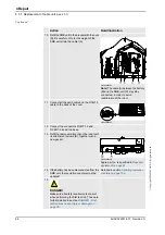
6. In order to release the brakes, connect the 24 VDC
power supply to the motor.
Note!
Release the brakes of the two motors, but one
at a time!
Connect to motor axis 5,
connector R3.MP5:
•
+ :pin 7
•
- : pin 8
Connect to motor axis 6,
connector R3.MP6:
•
+ : pin 7
•
- : pin 8
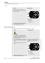
7. Fit the
measuring tool
at the rear of the motor.
8. Push the wrist, as shown in the figure to the right, to
locate the smallest play in the same way as for
adjustment of play when changing motors for axes 5
and 6, detailed in section
axes 4-6, IRB 2400/10/16 on page 144
xx0200000425
A. Gears on drive shaft unit,
axis 5-6
B. Gears on the wrist
9. Tighten the attachment screws and washers.
Tightening torque: 17 Nm.
10. Check the play by moving axes 5 and 6 by hand.
11. Refill the wrist unit with oil.
See the section
gearbox axes 5-6 (wrist unit) on
page 69
12. Recalibrate the robot.
Calibration is detailed in a
separate calibration manual,
enclosed with the calibration
tools.
General calibration information is
included in section
.
13.
DANGER!
Make sure all safety requirements are met when
performing the first test run. These are further
detailed in section
cause injury or damage! on page 35
.
Action
Note/Illustration
Continued
Summary of Contents for IRB 2400/10
Page 1: ...Product manual Articulated robot IRB 2400 L IRB 2400 10 IRB 2400 16 M2000 M2000A M2004 ...
Page 2: ......
Page 8: ...Table of Contents 6 3HAC022031 001 Revision C Copyright 2004 2008 ABB All rights reserved ...
Page 191: ......
Page 192: ......
Page 193: ......
Page 194: ......
Page 195: ......
Page 198: ......
Page 199: ......
Page 202: ......
Page 203: ......
Page 205: ......
Page 226: ......


